


Wiring and Connections - UDM Receivers
21
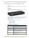
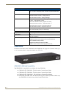
UDM-0404 Endeleo Multi-Format Distribution Hub
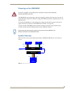
Connecting an IR Device to the IR Tx Port
1.
Connect an IR01 Endeleo IR Emitter Module (FG-IR01) to the IR Tx port on the UDM Receiver.
2. Run the other end of the IR Emitter cable to the device’s IR sensor, and attach the IR Emitter to the
device’s sensor by removing the cover on the reverse side of the IR Emitter.
IR commands for each device on the system have to be learned by the UDM Hub in order to function
properly. Refer to the Creating and Learning an IR Protocol section on page 66 for information on
learning a device’s IR commands.
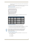
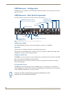
AUDIO Connectors
UDM Receivers provide standard Audio RCA output connectors for S/PDIF for digital audio, and
LEFT/RIGHT for analog audio output (see FIG. 13 on page 20).
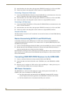
VIDEO Connectors
VGA Input at Display Device
1.
Attach one end of the Endeleo VGA to VGA cable to the VGA connector on the UDM Receiver.
2. Run the other end to the VGA connector on the display device. Connect firmly.
3. If appropriate connect audio to the audio connectors on the UDM Receiver.
Composite Input at Display Device
1.
Attach the composite cable (normally yellow) to the CVBS connector on the UDM Receiver.
2. Run the other end of the composite cable to the Composite connector (normally yellow) on the
display device. Connect firmly.
3. If appropriate connect audio to the audio connectors on the UDM Receiver.
SVideo Input at Display Device
1.
Attach the SVideo cable to the 4-pin S Video connector on the UDM Receiver.
2. Run the other end of the SVideo cable to the SVideo connector on the display device. Connect
firmly.
3. If appropriate connect audio to the audio connectors on the UDM Receiver.
Component Input at Display Device
1.
Attach the Component cables (normally green, blue and red) to the Y (green), Pb (blue) and Pr
(red) connectors on the UDM Receiver.
2. Run the other end of the Component cable to the Component connectors (normally green, blue and
red) on the display device. Connect firmly.
3. If appropriate connect audio to the audio connectors on the UDM Receiver.
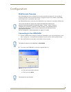
Ensure the position of the device corresponds to the position assigned in the Devices
option of the UDM- Hub’s WebConsole.
Ensure Input A is configured as a “VGA Input” and named appropriately within the
“Inputs” section of the Hub’s Configuration software. Also ensure the correct Audio
Type (Analog L/R or S/PDIF) is selected for the relevant input.