


Wiring and Connections
14
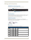
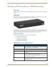
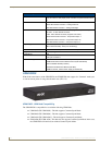
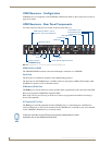
UDM-0404 Endeleo Multi-Format Distribution Hub
2. Attach the other end of the cable to the appropriate VIDEO IN connection (A or B) on the UDM.
3. Connect any audio to the analog (RCA) audio connectors or digital (SPDIF) connector.
Connecting a Component Video Input
1.
Connect the UDM-HD15RCA3 Breakout Cable (FG-HD15RCA3, not included) to the video source
device’s Component video output connectors (Red, Green and Blue).
2. Attach the other end of the cable to the appropriate VIDEO IN connection (A or B) on the UDM.
3. Connect any audio to the analog (RCA) audio connectors or digital (SPDIF) connector.
Connecting an S-Video Input
1.
Connect the UDM-SVID01 HD15 to SVideo cable (FG-UDM-SVID01, not included) to the video
source’s S-Video connection.
2. Attach the other end of the cable to the appropriate VIDEO IN connection (A or B) on the UDM.
3. Connect any audio to the analog (RCA) audio connectors or digital (SPDIF) connector.
Cascade In/Out Ports
The Ports labelled "Cascade In" and "Cascade Out" are reserved for future use. On the UDM-0404 they
are non-functional.
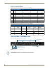
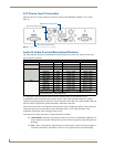
Device Connectivity (IR TX1/2 and TX3/4 Ports)
A maximum of 4 Devices such as DVD players or VCRs can be connected to the UDM Hub and
controlled through the Browser software or via a remote control. An (optional) IR02 IR splitter cable
(FG-IR02) may be required.
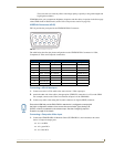
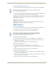
1. Connect an Endeleo IR Emitter Module (FG-IR01) to the relevant IRTX port at the rear of the Hub.
2. Run the other end of the IR Emitter to the device’s IR sensor and attach the bud to the device’s
sensor by removing the cover of the reverse side of the bud.
IR commands for each device on the system have to be learned by the Hub in order to function properly.
Refer to the Protocols and IR section of the UDM-0404 Operation/Reference Guide on how to learn a
device’s IR commands.
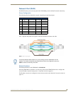
Connecting UDM RX01/RX02 Receivers to the UDM-0404
1. Connect a standard Cat5/6 cable to the port marked UDM on the UDM Hub.
2. Connect the other end of the Cat5/6 cable to the “UDM Hub” port on the UDM-RX01 or RX02
Receiver.
3. When the power is switched on 2 LEDs will be visible at the Hub port – Amber (phantom power
enabled) and Green (UDM receiver connected to Hub port).
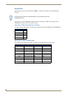
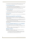
IEC Power Connector
The UDM-0404 uses a universal switch-mode power supply, which operates from 90-264V AC,
50/60Hz, with a power consumption of 130W fully loaded.
The rating label found to the bottom left of the UDM-0404, beneath the IEC connector,
contains important information applicable to the UDM-0404's installation environment.
The Power On/Off switch is located beside the IEC power connector.