


13
2.5 Connecting Power
Important:
Carefully review the power requirements (Chapter 2.1.3) before connecting power to the switch.
Use the following procedure to connect power to the switch:
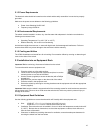
1. Plug one end of the supplied power cord into the power connector on the back of the switch.
2. Plug the other end into a grounded AC outlet.
3. Turn on the switch’s power. The power LED will begin its initialization process.
The front panel LEDs blink and the power LED illuminates when it has initialized. The switch is ready for
connection to the network.
Important: If the power does not come on, check the next section to ensure that the correct cabling is used.
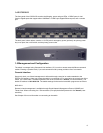
2.6 Connecting to the Network
The switch may be connected to an Ethernet network with the switch powered on or off.
Use the following
procedure to make the network connections:
1. Connect the network devices to the switch, following the cable guidelines outlined below.
2. After the switch is connected to the network, it can be configured for management capabilities (see
the following chapters for information on configuration).
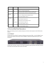
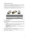
2.6.1 10/100/1000BaseT Ports Cabling Procedures
The 10/100/1000 ports on the switch allow for the connection of 10BaseT, 100BaseTX, or 1000BaseT
network devices. The ports are compatible with IEEE 802.3 and 802.3u standards.
Important: The switch must be located within 100 meters of its attached 10BaseT or 100BaseTX devices.
Use the following guidelines to determine the cabling requirements for the network devices:
•
Connecting to Network Station: Category 5 UTP (Unshielded Twisted-
Pair) straight-through cable (100 meters maximum) with RJ-45 connectors
•
Connecting to Repeater/Hub/Switch’s Uplink port: Category 5, UTP
straight-through cable (100 meters maximum) with RJ-45 connectors
Note: These switches have no specific uplink ports. All 10/100/1000 ports on these
switches are auto-sensing MDI/MDI-X. This advanced feature means that when the
ports are operating at 10/100Mbps, they will automatically determine whether the device at the other end of
the link is a hub, switch, or workstation, and adjust its signals accordingly. No cross-over cables are
required.
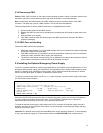
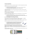
Although 10/100BaseT requires only pins 1, 2, 3, and 6, Asanté strongly recommends cables with all 8 wires
connected as shown in Table 2-2 below.