


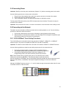


14
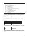
1000BaseT requires that all four pairs (8 wires) be connected correctly, using Category 5 or better
Unshielded Twisted Pair (UTP) cable (to a distance of 100 meters). Table 2-2 shows the correct pairing of all
eight wires.
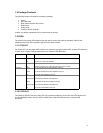
Pin Number
Pair Number & Wire Colors
1
2 White/Orange
2
2 Orange/White
3
3 White/ Green
4
1 Blue/White
5
1 White/Blue
6
3 Green/White
7
4 White/Brown
8
4 Brown/White
Table 2-2 Pin Numbers and Wire Colors
2.6.2 Gigabit Ethernet Ports Cabling Procedures
Cabling requirements for the optional hardware modules depend on the type of module installed. Use the
following guidelines to determine the particular cabling requirements of the module(s):
•
1000BaseSX GBIC: Cables with SC-type fiber connectors; 62.5-micron multi-mode fiber (MMF)
media up to 275 meters (902 feet) long, or 50-micron MMF media up to 550 meters (1805 feet)
long
•
1000BaseLX GBIC: Cables with SC-type fiber connectors; 10-micron single-mode fiber media up to
5 kilometers (16,405 feet) long
•
1000BaseLH GBIC: Cables with SC-type fiber connectors; 10-micron single-mode fiber media up to
20 kilometers (65,617 feet) long
•
1000BaseLX Long Haul GBIC: Cables with SC-type fiber connectors; 10-micron single-mode fiber
media up to 100 kilometers (328,100 feet) long
•
1000BaseLZ GBIC: Cables with SC-type fiber connectors; 10-micron single-mode fiber media up to
120 kilometers (393,701 feet) long
•
1000BaseT: Category 5 or better Unshielded Twisted Pair (UTP) cable to a distance of 100 meters
(328.1 feet) long
When attaching a workstation to the switch, a standard straight-through CAT5 cable may be used, even
when the workstation is attached via a patch panel. No crossover cable is needed with the MDX/MDI ports.
It is recommended that the switch be kept off the network until proper IP settings have been set.
2.7 Setup
In order to configure the switch, connect to it through a console (out-of-band management), running a
terminal emulation program, such as HyperTerminal.
2.7.1 Connecting to a Console
To connect the switch to a console or computer, set up the system in the following manner:
1. Plug power cord into the back of switch.
2. Attach a straight-through serial cable between the RS232 console port and a COM port on the PC.
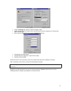
3. Set up a HyperTerminal (or equivalent terminal program) in the following manner:
• Open the HyperTerminal program, and from its file menu, right-click on Properties
• Under the
Connect To
tab, choose the appropriate COM port (such as COM1 or COM2)