


2-322-32
2-322-32
2-32
Chapter 2: Hardware informationChapter 2: Hardware information
Chapter 2: Hardware informationChapter 2: Hardware information
Chapter 2: Hardware information
9.9.
9.9.
9.
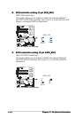
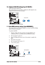
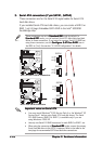
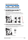
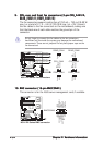
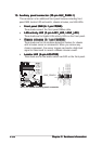
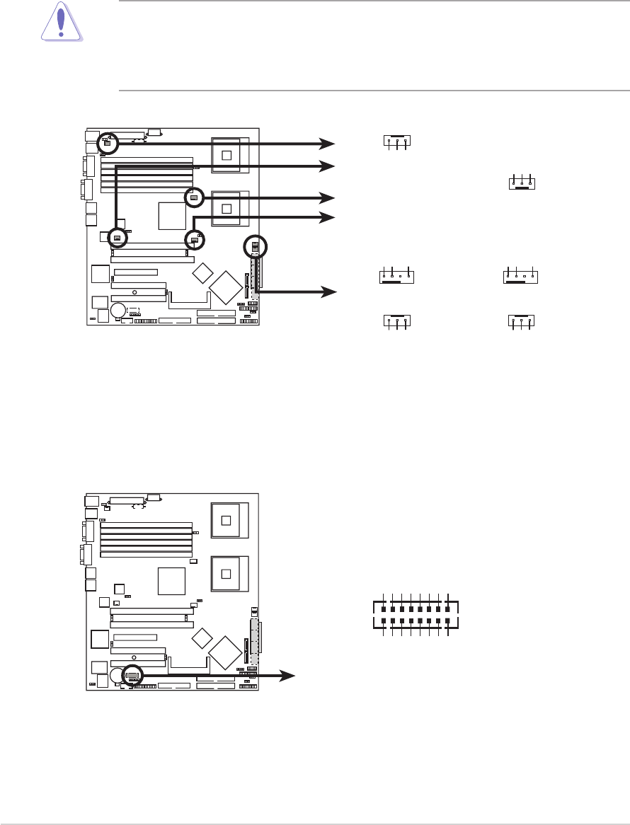
CPU, rear, and front fan connectors (3-pin CPU_FAN1/2,CPU, rear, and front fan connectors (3-pin CPU_FAN1/2,
CPU, rear, and front fan connectors (3-pin CPU_FAN1/2,CPU, rear, and front fan connectors (3-pin CPU_FAN1/2,
CPU, rear, and front fan connectors (3-pin CPU_FAN1/2,
REAR_FAN1/2, FRNT_FAN1/2)REAR_FAN1/2, FRNT_FAN1/2)
REAR_FAN1/2, FRNT_FAN1/2)REAR_FAN1/2, FRNT_FAN1/2)
REAR_FAN1/2, FRNT_FAN1/2)
The fan connectors support cooling fans of 350 mA ~ 740 mA (8.88 W
max.) or a total of 2.1 A ~ 4.44 A (53.28 W max.) at +12V. Connect
the fan cables to the fan connectors on the motherboard, making sure
that the black wire of each cable matches the ground pin of the
connector.
Do not forget to connect the fan cables to the fan connectors.
Insufficient air flow inside the system may damage the motherboard
components. These are not jumpers! Do not place jumper caps on the
fan connectors!
NCLV-D2 Series Fan connectors
GND
Rotation
+12V
REAR_FAN2REAR_FAN1
FRNT_FAN1 FRNT_FAN2
GND
Rotation
+12V
CPU_FAN2
REAR_FAN2
REAR_FAN1
FRNT_FAN1
FRNT_FAN2
CPU_FAN1
GND
FANPWR2
FANOUT4
CPU_FAN2CPU_FAN1
GND
FANPWR2
FANOUT4
GND
Rotation
+12V
GND
Rotation
+12V
10.10.
10.10.
10.
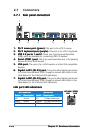
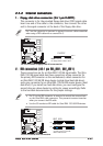
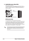
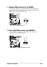
BMC connector (16-pin BMCCONN1)BMC connector (16-pin BMCCONN1)
BMC connector (16-pin BMCCONN1)BMC connector (16-pin BMCCONN1)
BMC connector (16-pin BMCCONN1)
This connector is for the ASUS server management card, if available.
NCLV-D2 Series BMC connector
BMCCONN1
+5VSB
+5VSB
BMC SMBCLK
12CCLK1
PSON#
BMC_RST#
PWROK
PSONEN#
+5VSB
+5VSB
BMC SMBDATA
12CDATA1
FP_PWRBTN#
BMC_PRESENT#
BMC_SMI#
GND