


DS62-Network, DS62-MD4 Network/Modem Host Module
12
Cabling
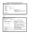
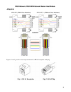
RJ-45 Cables and Adapters
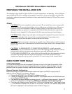
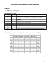
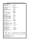
DS62 EIA-232 RJ-45 Signal
Pin EIA 232
Signal
Signal
Direction
Description
1 DTR Out Handshake, Line Driver Inactive State = High: +12V when power is
applied. Used as a handshake line to enable/disable the receiving of
characters.
2 GND Signal Ground
3 RTS Out Handshake, Line Driver Inactive State = High: +12 V when power is
applied. Not used to enable/disable.
4 TX Out Transmit Data Out
5 RX In Receive Data In
6 DSR In Handshake In. –12V when not used.
7 GND Signal Ground
8 CTS In Used as a handshake line to enable/disable the receiving of characters.
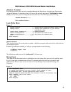
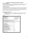
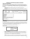
Adapters Signals
Listed are the pin
specifications for the BayTech cable and adapters and the terminal COM ports:
Signal RS-232
Port (DS)
RS-232
Port (RPC)
COM Port
DE-9 Pin
COM Port
DB-25 Pin
Signal
DTR 1 1 4 20 DSR
GND 2 2 1 GND
RTS 3 3 7 5 CTS
TXD 4 4 3 2 RXD
RXD 5 5 2 3 TXD
DSR 6 N/C 6 6 DTR
GND 7 7 5 7 GND
CTS 8 8 4 RTS
DTR 4 DCD
DCD 8 1 8 DTR
RI 9 22