


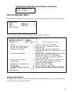

DS62-Network, DS62-MD4 Network/Modem Host Module
19
Stop Bits
The Stop Bits are used to signal the end of communication for a single packet. Since the data is
clocked across the lines and each device has its own clock, it is possible for the two devices to become
slightly out of sync. Therefore, the stop bits not only indicate the end of transmission but also give the
computers some room for error in the clock speeds. The more bits that are used for stop bits, the
greater the lenience in synchronizing the different clocks, but the slower the data transmission rate.
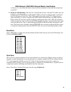
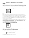
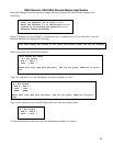
Select “Stop Bits” the DS displays the following: Default is 1.
Parity
Parity is a simple form of error checking used in serial communication. For even and odd parity, the
serial port will set the parity bit (the last bit after the data bits) to a value to ensure that the transmission
has an even or odd number of logic high bits. For example, if the data was 011, then for even parity,
the parity bit would be 0 to keep the number of logic high bits even. If the parity was odd, then the
parity bit would be 1, resulting in 3 logic high bits. This allows the receiving device to know the state
of a bit so as to enable the device to determine if noise is corrupting the data or if the transmitting and
receiving devices' clocks are out of sync.
With no parity selected, it's assumed that there are other forms of checking that will detect any errors
in transmission. No parity also usually means that the parity bit can be used for data, speeding up
transmission. In modem-to-modem communication, the type of parity is coordinated by the sending
and receiving modems before the transmission takes place.
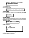
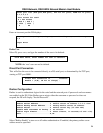
Select “Parity” the DS displays the following: Default is None.
RTS/DTR Line Driver Inactivity State
RTS (Request to Send)/ DTR (Data Terminal Ready) is normally used in conjunction with an external
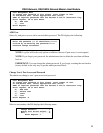
modem. With no modem the RTS and DTR default state is High.
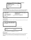
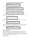
Select “RTS Driver State” the DS displays the following:
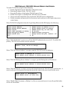
Select “DTR Driver State” the DS displays the following:
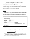
Select stop bits:
1 For 1
2 For 1.5
3 For 2
Enter Request :
Select parity:
1 For None
2 For Even
3 For Odd
Enter Request :
RTS Line Driver Inactive State is: High
High ? (Y/N, CR for no change):