3-32
Confidential
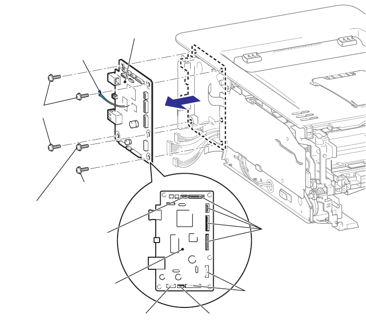
8.13 MAIN PCB ASSY
(1) Disconnect the six FFCs and the three Connectors from the Main PCB ASSY.
(2) Remove the four Taptite cup S M3x6 SR screws, and then remove the FG harness
ASSY and Main PCB ASSY from the Main body.
Memo :
The five Taptite cup S M3x6 SR screws. (HL-2150N/2170W only)
Fig. 3-26
Assembling Note:
If the FG harness ASSY which comes from the Laser unit is not connected, the Laser unit
break down.
FG harness ASSY
Taptite cup S M3x6 SR
Taptite cup S M3x6 SR
(Only HL-2150N/2170W)
FFC
FFC
FFC
Connector
Connector
Taptite cup S M3x6 SR
Main PCB ASSY
Main PCB ASSY


