


3-39
Confidential
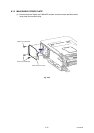
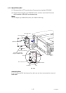
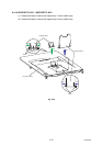
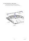
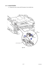
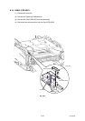
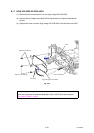
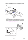
8.17 HIGH-VOLTAGE PS PCB ASSY
(1) Disconnect the two connectors from the High-voltage PS PCB ASSY.
(2) Remove the two Taptite cup S M3x6 SR screws and the two Taptite bind B M4x12
screws.
(3) Release the Hook to remove High-voltage PS PCB ASSY from the Drive sub ASSY.
Fig. 3-33
Note:
There are procedures for disassembling Main frame L ASSY after this procedure.
(8.31 MAIN FRAME L ASSY)
High-voltage PS PCB ASSY
Drive sub ASSY
Hook
Taptite bind B M4x12
Taptite cup S M3x6 SR
Connector
3
1