


2001/10/02
CHAPTER 3 "PCL5C" - 5
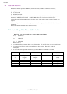
2.2. Using PCL Color Mode - Set PCL Color Setting
Command
ESC*v#W (27)(42)(118)#(87) <1Bh><2Ah><76h>#<57h>
# = 6, 18
# stands for the number of bytes of data that follow this command.
This command sets the palette size and transformation between the entered value and device-specific value.
This command has two types of format, short format and long format. Here are the formats for the PCL color
setting.
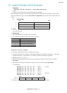
1) Short Format
MSB
LSB
0 - 1
Format (0) Encoding mode
2 - 3
Bits / index Bits / value #1
4 - 5
Bits / value #2 Bits / value #3
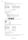
♣ Format
This value must be 0.
♣ Encoding mode
• This value defines how to send the raster image data.
• The value can be from 0 to 3 only, other values are ignored.
Encoding Mode
0 Send Index No by Plane *
1 Send Index No by Pixel
2 Send Direct Value by Plane
3 Send Direct Value by Pixel
* = default
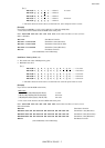
Send Index No by Plane (= 0 default)
• This mode assigns the Index No. to the Plane, then sends it.
• The necessary number for the Plane is determined depending on the number of bits/index. 1 (one) plane
should be needed per 1 (one) bit/index. For instance, 4 planes are needed for 4 bits/index.
• Bits/index must be 1, 2, 4, 5, 6, 7, 8.
• This mode sends the plane data except the last one using the Send Raster Data by Plane command
(ESC*b#V).
• This mode also sends the last plane data using the Send Raster Data command (ESC*b#W).
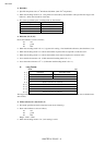
(i.e. 4 bits/index)
ESC*b#V d1, d1, d1, d1, d1 ...→ Plane 1 1st raster
ESC*b#V d2, d2, d2, d2, d2 ...→ Plane 2
ESC*b#V d3, d3, d3, d3, d3 ...→ Plane 3
ESC*b#W d4, d4, d4, d4, d4 ...→ Plane 4
ESC*b#V d1, d1, d1, d1, d1 ...→ Plane 1 2nd raster
ESC*b#V d2, d2, d2, d2, d2 ...→ Plane 2
MSB LSB
Index No.
d4 d3 d2 d1
** The Italic characters shown above are the index No. at the 4th pixel in the 1st raster.