


Confidential
2-22
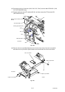
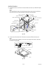
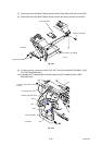
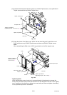
(7) Secure the two cup S M3x8 Taptite screws onto the front side of the Joint cover ASSY.
(8) Secure the two cup S M3x8 Taptite screws onto the left side of the Joint cover ASSY.
Fig. 2-34
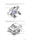
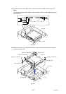
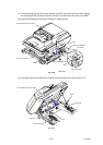
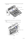
(9) Connect the four Connectors (CN2, CN3, CN7, CN10) into the Main PCB ASSY. (CN2,
CN7: MFC-9840CDW only)
(10) Assemble the FG harness NCU with the Screw pan (S/P washer) M3.5x6. (MFC-
9840CDW only)
Fig. 2-35
Joint cover ASSY
Taptite, cup S M3x8
Taptite, cup S M3x8
<Front>
<Left side>
Taptite, cup S M3x8
Main PCB ASSY
CN10
CN7
CN3
FG harness NCU
Screw pan (S/P washer)
M3.5x6
CN2
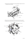
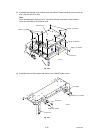
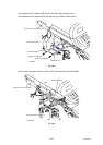
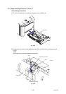
Develop gear plate
ASSY
<Left side>