


Confidential
3-203
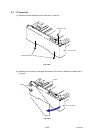
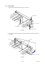
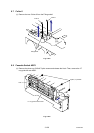
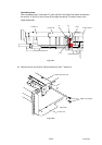
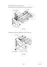
Assembling Note:
When assembling the F roller shaft LT, place the Rib of the Paper feed frame unit between
the section “A” and “B” of the Lift lever B and align the section “B” with the Lever of the
Paper feed holder.
Fig. 3-311
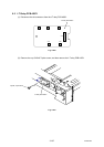
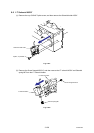
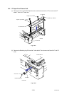
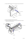
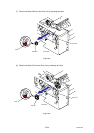
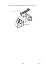
(6) Remove the two cup S M3x6 Taptite screws from the LT frame unit.
Fig. 3-312
Taptite, cup S M3x6
LT paper feed frame unit
LT frame unit
<Right side>
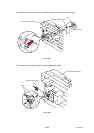
Lift lever A
Lift lever B
“B”
“A”
F roller shaft LT
Paper feed frame unit
Paper feed holder
Rib
Lever