


Confidential
3-118
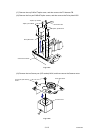
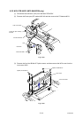
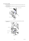
8.24 Joint Cover ASSY
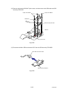
(1) Remove the bind B M4x12 Taptite screw, and then remove the Pull arm guide L from the
Joint cover ASSY.
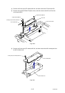
(2) Remove the bind B M4x12 Taptite screw, and then remove the Pull arm guide R from the
Joint cover ASSY.
Fig. 3-154
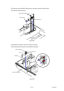
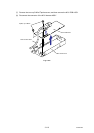
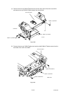
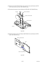
(3) Disconnect the two Connectors (CN2, CN3) from the Main PCB ASSY. (CN2: MFC-
9840CDW only)
Fig. 3-155
Pull arm guide L
Joint cover ASSY
Taptite, bind B M4X12
Main PCB ASSY
CN2
CN3
Side frame L
<Left side>