


Confidential
2-25
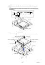
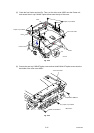
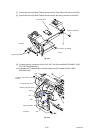
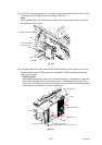
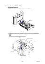
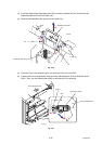
(17) Put the Flat cable through the Core, and then connect the three Connectors (CN14, CN16,
CN21) and one Flat cable (CN17) into the Main PCB ASSY.
Note:
When connecting the Flat cable(s), do not insert it at an angle. After insertion, check that
the cable is not at an angle.
Fig. 2-40
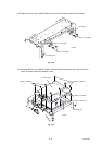
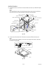
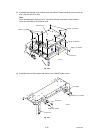
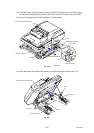
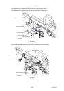
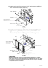
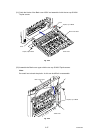
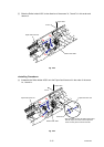
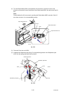
(18) Catch the Hooks of the Side cover R ASSY with the main body in the order of 18a to 18e
and fix the Side cover R ASSY with the two cup B M4x12 Taptite screws and two cup S
M4x8 Taptite screws.
*1
Tightening Note:
When tightening the screw, slowly turn it counterclockwise (in the direction to loosen the
screw) with your hand until you feel that the screw is a little dropped in the hole. Then,
slightly turn it clockwise (in the direction to tighten the screw) with your hand and tighten
it according to the specified torque with a screwdriver.
Fig. 2-41
Taptite, cup S M4x8
Hooks
Side cover R ASSY
Taptite, cup S M4x8
Taptite, cup B M4x12
(Tightening torque: 1.20 ±0.1 N m) *1
Hooks
<Right side>
18a
18b
18c
18d
18e
Hook
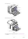
Document scanner unit ASSY
Main PCB ASSY
CN14
CN21
Flat cable (CN17)
CN16
<Left side>
Core