SmartSwitch 6500 User Guide 2-19
Switch Installation and Setup LED Descriptions
2.4 LED DESCRIPTIONS
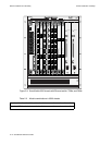
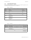
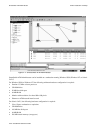
Both the CSM and TSM modules display several LED indicator lights. Table 2-3 and Table 2-4 explain the color, state,
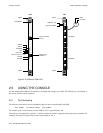
and meaning of the CSM and TSM indicator lights. Also, see Figure 2-10.
Table 2-3 CSM LEDs
LED Green Amber Red Unlit
POWER Power on No power
ACTIVE CSM is active CSM not active
*
STANDBY CSM is in standby
mode
CSM is not in standby
mode
FAIL CSM is in fail Normally off
ENET RDY Ethernet interface is
up and active
Ethernet interface not
active
*
TX DATA Normally flashing,
transmitting data on
Ethernet port
RX DATA Normally flashing,
receiving data on
Ethernet port
*
Slave CSM
Table 2-4 TSM LEDs
LED Green Amber Red Unlit
TSM FAIL/OK TSM is initialized TSM not initialized
CPU FAIL/OK CPU in active mode CPU in standby mode
*
CPU in fail No CPU on TSM
DATA Normally flashing when
connected, data is
passing through the port
No data is passing
through port.
NO SYNC Framer is not receiving
sync
Normally off when
connected, Framer
is receiving sync
*
Slave TSM/CPU


