


6-4 SmartSwitch 6500 User Guide
PVP Connections Virtual Ports and Static Connections
6.1.3 Connecting to Local Switch Client Through a PVC
All PVC connections to the SmartSwitch 6500 local clients use the CPU port. This port is either 7b4 or 8b4 depending
on the slot in which the master TSM/CPU module resides.
Follow these instructions to connect an end node to a SmartSwitch 6500 local client through a point-to-point PVC.
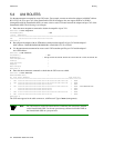
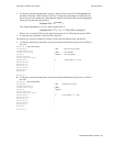
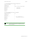
1. Use add pvc to create the PVC.
Smart6500 # add pvc
ConnType(PTP) :
Port-1-Number() : 7a1
Port-1-VPCI() : 0
Port-1-VCI() : 100
Port-2-Number() : 7b4
< The CPU port
Port-2-VPCI() : 0
Port-2-VCI() : 100
Port1-to-Port2TrafficDescriptorIndex() : 2
Port2-to-Port1TrafficDescriptorIndex() : 2
Smart6500 #
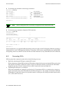
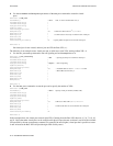
2. Use add ipatmclient to create the IP over ATM local client.
Smart6500 # add ipatmclient
ClientNumber(0) : 2
< Set client number 2
ServerType(None) : local
< ARP server is on the switch
ServerAddress() :
IPAddress() : 100.1.1.0
NetMask(255.0.0.0) :
MTU(9180) :
Smart6500 #
3. Use add ipatmpvc to associate the end node’s IP address with the PVC.
Smart6500 # add ipatmpvc
ClientNumber(0) : 2
< Specify local client number
DestinationIP() : 100.1.1.22
< End node’s IP address
DestinationVPI(0) :
DestinationVCI(33) : 100
<VCI was specified as 100
Smart6500 #
4. Connect the end node to port 7a1 of the SmartSwitch 6500.
5. Configure the end node with IP address 10.1.1.22, subnet mask 255.0.0.0, and VPI/VCI pair = 0/100.
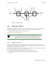
6.2 PVP CONNECTIONS
The SmartSwitch 6500 supports the creation of Permanent Virtual Path (PVP) connections. The basic process for
creating a PVP is as follows:
•
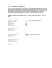
Create a traffic descriptor for the PVP that meets its bandwidth and service category requirements.
•
Use the set portconfig command to turn off signaling and ILMI on both ports to be connected by
the PVP.
Note Dedicated PVP switches do not signal on their physical ports. However, you can
leave signaling active on physical ports on the SmartSwitch 6500 if desired.