4-4 SmartSwitch 6500 User Guide
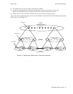
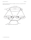
Multi-level PNNI Topology PNNI Routing
Note The first byte of the peer group ID indicates the peer group’s level. It also indicates
the number of significant bits used in the peer group ID. For example, if the level
indicator is 50 (80 decimal), then 80 bits / 8 = 10 bytes; and only 10 of the 13 bytes
are significant (39:00:00:00:00:00:00:00:00:00). If you create a new peer group
ID, make sure that the bytes you change are within the range of significant bytes
for the peer group’s level.
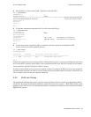
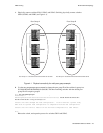
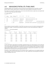
3. Use the show pnnilink command to check the PNNI connectivity within each peer group. For
example, switch SWA3 sees links to the other two members of its peer group:
A3 # show pnnilink
Num(ALL) :
Num Port Node Remote Node Hello State Link Type
Number Index IP Addr
===========================================================================
1 7A2 1 206.61.237.20 2WayInside Lowest Level Horizontal Link
2 7A3 1 206.61.237.19 2WayInside Lowest Level Horizontal Link
A3 #
4. Select switch SWA3 to be the PGL of group A and switch SWB3 to be the PGL of group B.
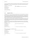
5. Use the add pnninode command to add a second, higher-level, node to switch SWA3:
A3 # add pnninode
NodeIndex(2) :
< Specifies node number 2
NodeLevel(72) :
< 72 is above the group A’s level of 80
ComplexRepresentation(N) :
A3 #
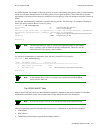
Do the same for switch SWB3:
B3 # add pnninode
NodeIndex(2) :
< Specifies node number 2
NodeLevel(72) :
< 72 is above the group B’s level of 80
ComplexRepresentation(N) :
B3 #
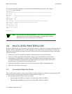
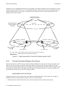
6. Use the set pnnipglelection command to set SWA3 and SWB3’s leadership priority so that they
are elected as PGLs within their respective peer groups:
A3 # set pnnipglelection
NodeIndex(1) :
LeadershipPriority(0) : 205
< Highest priority in election process
ParentNodeIndex(0) : 2
< Node 2 will represent the peer group A in the parent group
InitTime(15) :
OverrideDelay(30) :
ReElectTime(15) :
A3 #


