


2-20 SmartSwitch 6500 User Guide
Using the Console Switch Installation and Setup
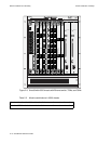
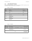
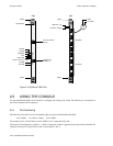
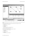
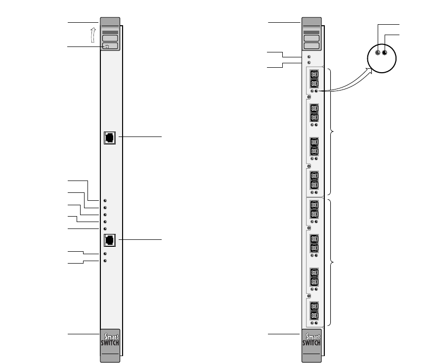
Figure 2-10 CSM and TSM LEDs
2.5 USING THE CONSOLE
Use the SmartSwitch 6500 console interface to configure and manage your switch. The following is a description of
the console interface and its operation.
2.5.1 Port Numbering
The following convention is used for numbering physical ports on the SmartSwitch 6500:
slot number I/O module letter port number
For example, port 3 of I/O module A on the TSM in slot 5 is represented by: 5A3
Virtual ports are designated by a period (.), and the virtual port number is appended to the physical port number. For
example, virtual port 2 on physical port
7B1 is represented as: 7B1.2
ATM
COM
ENET
POWER
ACTIVE
STANDBY
FAIL
ENET RDY
TX DATA
RX DATA
CSM
Console Terminal
(RJ-45)
Ethernet Port
(10Base-T)
POWER
ACTIVE
STANDBY
FAIL
ENET RDY
TX DATA
RX DATA
Reset Button
Ejector
Ejector
(Ethernet interface ready)
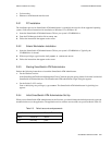
ATM
FAIL/MODECPU
FAIL/OKTSM
NO SYNC
DATA
123
4
6A-IOM-21-4
NO SYNC
DATA
123
4
6A-IOM-21-4
B
TSM
NO SYNC
DATA
I/O Module
I/O Module
NO SYNC
DATA
Ejector
TSM FAIL / OK
CPU FAIL / MODE
Ejector