


SmartCell ZX-250 User Guide B-1
APPENDIX B SPECIFICATIONS
This appendix contains SmartCell ZX-250 switch hardware, product features, technical specifications, and adapter
pin-out descriptions.
$•s )832:˜6"2'/
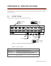
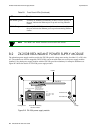
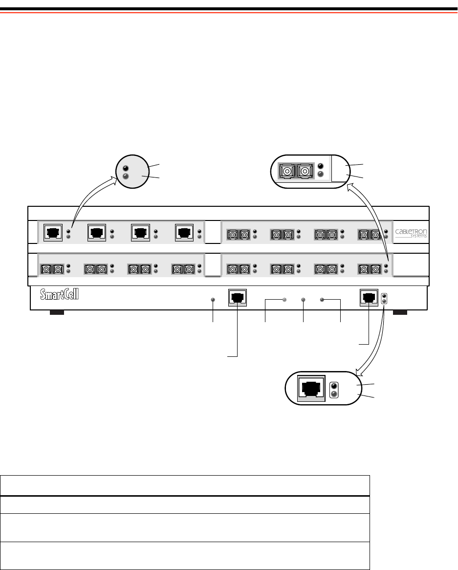
Figure B-1 illustrates the front panel of the SmartCell ZX-250 switch:
Figure B-1 Front panel of the SmartCell ZX-250 ATM switch
Table B-1 Front Panel LEDs
LED Function
FAIL (red) Normally OFF; ON indicates CPU failed.
STATUS (amber) Normally OFF; ON indicates an error condition that prevents
alarm information from being displayed to the console.
POWER (green) Normally ON; OFF indicates the CPU is not receiving power from
the power supply.
NO SYNC
DATA
MON
DIAG
RX DATAPOWERSTATUSFAILRESET
TX DATA
TERMINAL ETHERNET
1 2 3 4
NO SYNC
DATA
1 2 3 4
NO SYNC
DATA
NO SYNC
DATA
1 2 3 4
C
A
D
B
RESET
Button
Console Terminal
(RJ-45)
Ethernet Port
(10Base-T)
FAIL STATUS POWER
RX DATA
TX DATA
MON
DIAG
NO SYNC
DATA
TEST
ZX-250
NO SYNC
DATA
MON
DIAG
4
TEST
RX DATA
TX DATA