


SmartCell ZX-250 User Guide xiii
LIST OF FIGURES
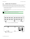
Figure 2-1 Front panel of a SmartCell ZX-250 ATM switch . . . . . . . . . . . . . . . . . . . . . . . . . . . . . . . . . . . . . . . . . 2-2
Figure 2-2 Rear view of ZX-250. . . . . . . . . . . . . . . . . . . . . . . . . . . . . . . . . . . . . . . . . . . . . . . . . . . . . . . . . . . . . . . 2-2
Figure 2-3 Rear view of ZX-250r with both power supply modules . . . . . . . . . . . . . . . . . . . . . . . . . . . . . . . . . . . 2-3
Figure 2-4 Airflow space for the ZX-250 in desktop environment . . . . . . . . . . . . . . . . . . . . . . . . . . . . . . . . . . . . 2-5
Figure 2-5 Attaching mounting brackets. . . . . . . . . . . . . . . . . . . . . . . . . . . . . . . . . . . . . . . . . . . . . . . . . . . . . . . . . 2-6
Figure 2-6 After brackets are attached, mount the switch in the rack. . . . . . . . . . . . . . . . . . . . . . . . . . . . . . . . . . . 2-7
Figure 2-7 Attaching mounting brackets. . . . . . . . . . . . . . . . . . . . . . . . . . . . . . . . . . . . . . . . . . . . . . . . . . . . . . . . . 2-9
Figure 2-8 After brackets are attached, mount the switch in the rack. . . . . . . . . . . . . . . . . . . . . . . . . . . . . . . . . . 2-10
Figure 2-9 ZX-250 console and network connections . . . . . . . . . . . . . . . . . . . . . . . . . . . . . . . . . . . . . . . . . . . . . 2-12
Figure 2-10 SmartSwitch ATM Administrator. . . . . . . . . . . . . . . . . . . . . . . . . . . . . . . . . . . . . . . . . . . . . . . . . . . . 2-18
Figure 4-1 IISP route across PNNI domain . . . . . . . . . . . . . . . . . . . . . . . . . . . . . . . . . . . . . . . . . . . . . . . . . . . . . . 4-4
Figure 4-2 Routes needed for a second IISP switch . . . . . . . . . . . . . . . . . . . . . . . . . . . . . . . . . . . . . . . . . . . . . . . . 4-4
Figure 4-3 IP routing through SW1for connectivity to the Ethernet network . . . . . . . . . . . . . . . . . . . . . . . . . . . .4-9
Figure 4-4 Memory locations affected by the boot load commands. . . . . . . . . . . . . . . . . . . . . . . . . . . . . . . . . . . 4-25
Figure 4-5 Internal components of the SmartCell ZX-250 ATM switch . . . . . . . . . . . . . . . . . . . . . . . . . . . . . . . 4-34
Figure 4-6 Remove the bezel from the chassis base. . . . . . . . . . . . . . . . . . . . . . . . . . . . . . . . . . . . . . . . . . . . . . . 4-35
Figure 4-7 Extractor lever arm function . . . . . . . . . . . . . . . . . . . . . . . . . . . . . . . . . . . . . . . . . . . . . . . . . . . . . . . . 4-35
Figure 4-8 Removing a switch module from the lower switch module position . . . . . . . . . . . . . . . . . . . . . . . . . 4-36
Figure 4-9 I/O module (installation/removal). . . . . . . . . . . . . . . . . . . . . . . . . . . . . . . . . . . . . . . . . . . . . . . . . . . . 4-37
Figure 4-10 Line up module on the nylon card guides. . . . . . . . . . . . . . . . . . . . . . . . . . . . . . . . . . . . . . . . . . . . . . 4-38
Figure 4-11 Push seated card in with even pressure. . . . . . . . . . . . . . . . . . . . . . . . . . . . . . . . . . . . . . . . . . . . . . . . 4-39
Figure 4-12 Complete seating of card with lever arms. . . . . . . . . . . . . . . . . . . . . . . . . . . . . . . . . . . . . . . . . . . . . . 4-40
Figure 4-13 Rear view of a ZX-250r redundant power supply module . . . . . . . . . . . . . . . . . . . . . . . . . . . . . . . . .4-41
Figure 4-14 Rear view of ZX-250r with single power supply module. . . . . . . . . . . . . . . . . . . . . . . . . . . . . . . . . . 4-42
Figure 4-15 Holding screw for power supply module . . . . . . . . . . . . . . . . . . . . . . . . . . . . . . . . . . . . . . . . . . . . . . 4-43
Figure 4-16 RPS module extraction and replacement . . . . . . . . . . . . . . . . . . . . . . . . . . . . . . . . . . . . . . . . . . . . . . 4-43
Figure 4-17 Pry out the fuse assembly.. . . . . . . . . . . . . . . . . . . . . . . . . . . . . . . . . . . . . . . . . . . . . . . . . . . . . . . . . . 4-44
Figure 4-18 Detail of fuse assembly. . . . . . . . . . . . . . . . . . . . . . . . . . . . . . . . . . . . . . . . . . . . . . . . . . . . . . . . . . . . 4-45
Figure B-1 Front panel of the SmartCell ZX-250 ATM switch . . . . . . . . . . . . . . . . . . . . . . . . . . . . . . . . . . . . . . .B-1
Figure B-2 ZX-250r power supply module . . . . . . . . . . . . . . . . . . . . . . . . . . . . . . . . . . . . . . . . . . . . . . . . . . . . . . .B-2
Figure C-1 Internet MIB hierarchy . . . . . . . . . . . . . . . . . . . . . . . . . . . . . . . . . . . . . . . . . . . . . . . . . . . . . . . . . . . . .C-2
Figure C-2 ZeitNet Private MIBs . . . . . . . . . . . . . . . . . . . . . . . . . . . . . . . . . . . . . . . . . . . . . . . . . . . . . . . . . . . . . .C-3