


2-2 SmartCell ZX-250 User Guide
Inspecting the Switch Switch Installation and Setup
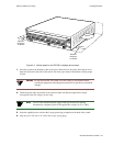
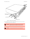
2.3 INSPECTING THE SWITCH
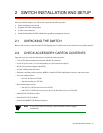
Depending on the configuration ordered, your switch looks similar to the drawing in Figure 2-1. You may have fewer
I/O modules than displayed in the drawing, in which case the missing modules are replaced by metal blanks.
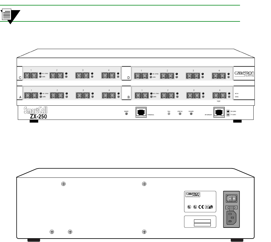
Inspect the switch and make certain that its configuration corresponds to what was ordered. Check the following:
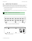
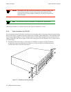
— Correct model number on the SmartCell ZX-250 switch sticker. On the ZX-250, the sticker is on the back. On
the ZX-250r, the sticker is on the bottom.
— Voltage rating on the power sticker.
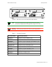
— Input/Output (I/O) modules are of the correct type and quantity. Check the ID numbers on the I/O module
faceplates (see Table 2-1).
2p›F All Single-Mode fiber connectors on I/O modules are blue.
Figure 2-1 Front panel of a SmartCell ZX-250 ATM switch
Figure 2-2 Rear view of ZX-250
THIS DEVICE COMPLIES WITH PART 15 OF THE FCC RULES.
OPERATION IS SUBJECT TO THE FOLLOWING TWO CONDITIONS:
(1) THIS DEVICE MAY NOT CAUSE HARMFUL INTERFERENCE, AND
(2) THIS DEVICE MUST ACCEPT ANY INTERFERENCE RECEIVED,
INCLUDING INTERFERENCE THAT MAY CAUSE UNDESIRED OPERATION.
LISTED
SP
16EO
ITE MULTIPORT
SWITCH UNIT
ZX-250
R R
C
CAUTION: FOR CONTINUED PROTECTION AGAINST RISK OF
FIRE, REPLACE ONLY WITH SAME TYPE AND RATING OF FUSE.
id
FUSE:
4A, 250V
SN
NET.
ADD.
LINE:
115V ~ 2.6A
60/50 Hz