


SmartCell ZX-250 User Guide 2-11
Switch Installation and Setup Switch Configuration
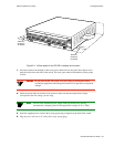
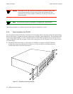
2p›F For information on power consumption, see Appendix B, “Specifications.”
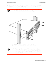
Rack installation for the ZX-250r is complete. Proceed to the next section: “Switch Configuration.”
2.5 SWITCH CONFIGURATION
Initial configuration of your ZX-250 switch consists of setting the name, Ethernet IP address, and subnet mask. Once
this is done, the switch can be reached for additional configuration and administration through your Ethernet network.
Perform the following steps to configure initial switch parameters:
s• Configure a dumb terminals or PCs running emulation software to use the following communication
parameters:
† Baud rate = 9600
† Data bits = 8
† Stop bits = 1
† Parity = none
† Flow Control = none
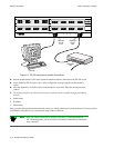
¢• Plug one end of the supplied RJ-45 UTP cable into the 9-pin COM port RJ-45 adapter.
2p›F For information about adapter wiring configurations, see Appendix B,
“Specifications.”
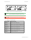
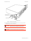
Plug the other end of the UTP cable into the ZX-250 female RJ-45 jack labeled Terminal, located at the bottom
center of the switch’s front panel (see Figure 2-9).
•• Connect the switch to your network by plugging a UTP cable into the ZX-250 female RJ-45 jack
labeled Ethernet, located at the lower right of the switch’s front panel (see Figure 2-9).