COPYRIGHT
©
2001 CANON INC. 2000 2000 2000 2000 CANON iR2200/iR2800/iR3300 REV.0 MAR. 2001
CHAPTER 2 SEQUENCE OF OPERATIONS
2-5 P
1.4 Controlling the Main Motor (M2)
1.4.1 Outline
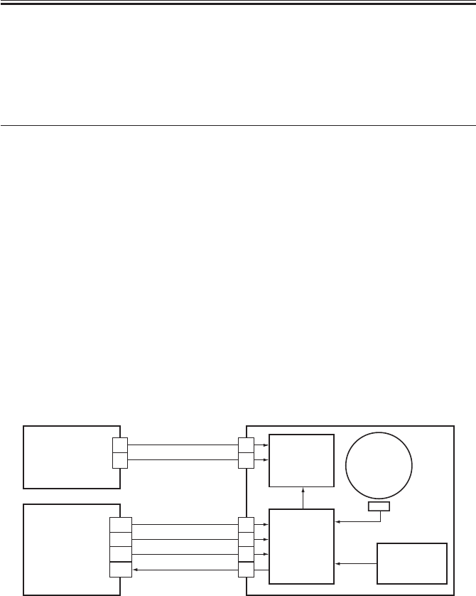
The functions of the main motor control circuit are as shown in T02-104-01; for a block
diagram of the circuit, see F02-104-01.
Item Description
Power supply 24 V from the DC power supply PCB.
Drive signal Signal (MM_ON) from the DC controller PCB.
Operation/drive assembly Waste toner feed screw
Cleaner assembly
Registration roller
Manual pickup assembly
Left deck feeding roller 2
Developing unit
Control ON/OFF control
Constant speed control
Error detection ‘E010’ (error code)
T02-104-01
[1] When the main motor drive signal (MM_ON) goes ‘1’, the main motor starts to rotate.
[2] When the main motor starts to rotate, the clock pulse signal (MM_LOCK=1) is gener-
ated. If the DC controller PCB detects a fault in the clock pulse signal, the machine will
indicate ‘E010’ in its control panel.
F02-104-01 Control Circuit Block Diagram
Drive circuit
Control
circuit
Reference
signal gene-
ration circuit
Clock pulse
generation
circuit
J3086
J3088
J308
J202
DC controller
PCB
Main power
supply PCB
1
2
1
2
3
4
1
2
A10
A9
A8
A7
24VU1-SW
MM_ON
MM_LOCK
0VU1
GND
+5V
Main motor
(M1)


