COPYRIGHT
©
2001 CANON INC. 2000 2000 2000 2000 CANON iR2200/iR2800/iR3300 REV.0 MAR. 2001
CHAPTER 7 EXTERNALS AND CONTROLS
7-13 P
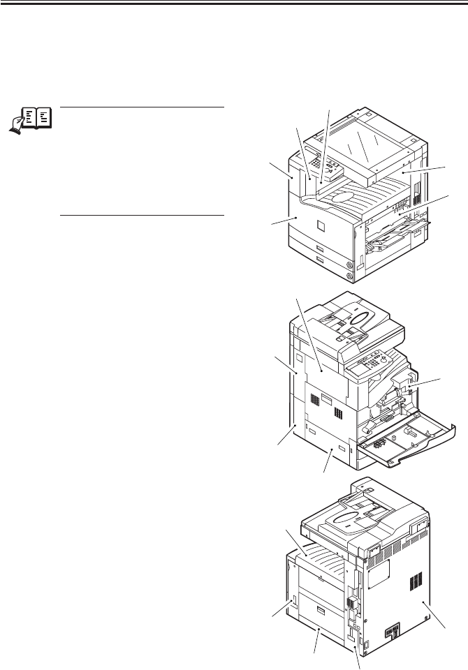
5.1 External Covers
Remove the covers as needed when
cleaning, checking, or repairing the inside
of the machine.
REF.
Those covers that can be de-
tached by mere removal of
mounting screws are left out of
the discussions. Unless other-
wise noted, the number in pa-
rentheses indicates the number
of mounting screws used.
[1] Support cover (1 screw)
[2] Support the right cover (1 screw)
[3] Left rear cover
[4] Rear cover (4 screws)
[5] Front cover (2 L-shaped pins)
[6] Delivery tray (2 screws)
[7] Inside cover (6 screws)
[8] Right front cover (2 screws)
[9] Right lower cover (not in Cassette
Feeding Unit-W1)
[10]Right rear cover (5 screws)
[11]Left upper cover (2; not in Finisher-J1
or Inner 2Way Tray-A1)
[12]Left lower cover (1 screw)
[13]Left rear cover (1 screw)
[14]Waste toner case cover (1 screw)
[15]Rear cover (7 screws)
[16]Right inside cover (7 screws)
F07-501-01
[1]
[2]
[3]
[4]
[5]
[6]
[7]
[8]
[9]
[10]
[11]
[12]
[13]
[15]
[14]
[16]


