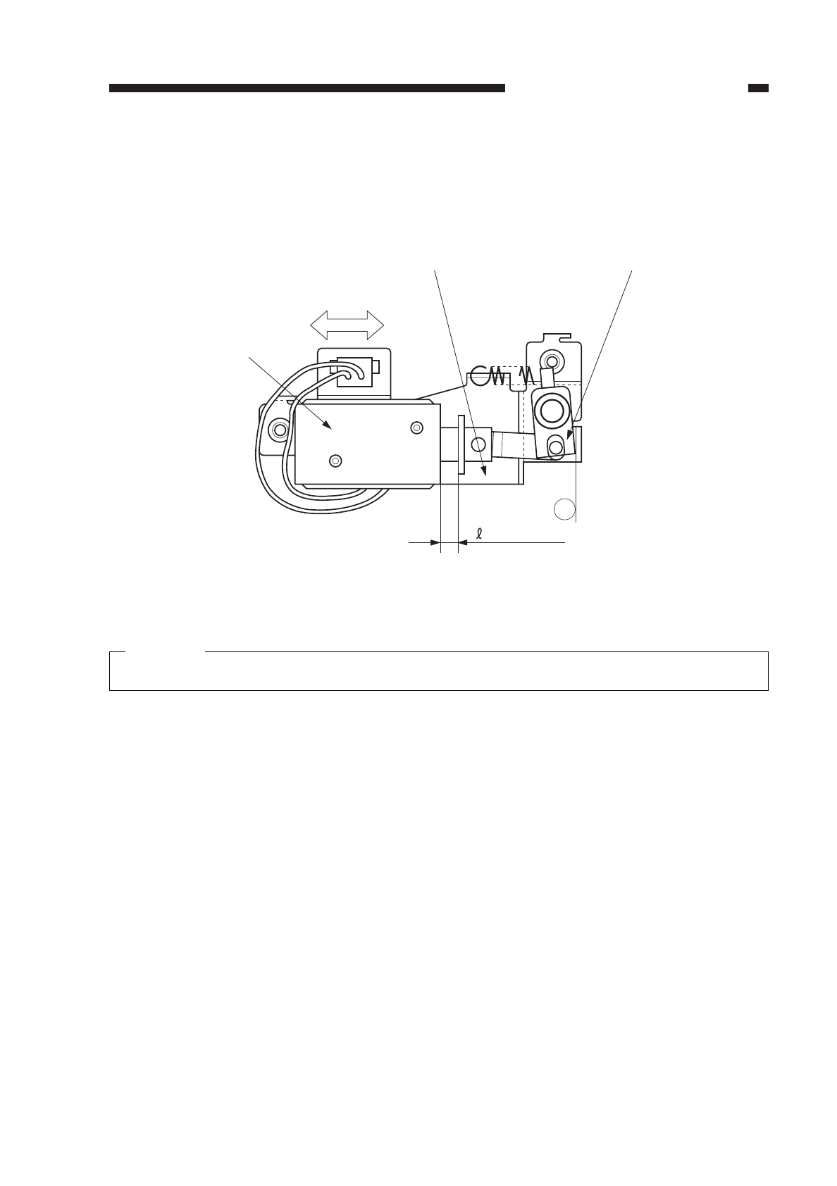
3. Positioning the Solenoid for the Primary Charging Roller
Make adjustments by loosening the two screws used to fix the solenoid e in place
and moving the solenoid e into the direction of arrow B so that
r in Figure 4-323 is 4.0
±0.2 mm when the joint q is butted against point a of the solenoid support w.
Figure 4-323
Caution:
You must make the adjustment whenever you have replaced the solenoid.
COPYRIGHT
©
1997 CANON INC. CANON NP6218 REV. 0 MAY 1997 PRINTED IN JAPAN (IMPRIME AU JAPON)
CHAPTER 4 IMAGE FORMATION SYSTEM
4-43
a
= 4.0 ± 0.2
B
w
q
e


