


D. Main Motor Control Circuit
1. Outline
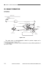
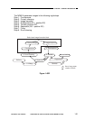
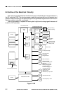
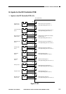
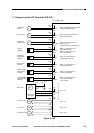
Figure 2-104 shows the circuit used to control the main motor (M1); the circuit has
the following functions:
q turns on and off the main motor.
w controls the main motor to a specific rotation speed.
The main motor (M1) is a DC motor that has a built-in clock pulse generator. When
the motor rotates, it generates clock pulse signals (MMCLK*) according to the revolution
of the motor. The speed control circuit matches the phases of the frequency of these
clock pulses and that of the reference signals to control the main motor (M1) to a specific
revolution speed.
2. Mechanism
When the main motor drive signal (MMD) from the DC controller circuit goes ‘1’, the
drive circuit of the motor driver turns on, thereby rotating the main motor (M1) at a
constant speed.
While the main motor is rotating at a specific speed, the motor driver PCB keeps
sending the specific speed state signal=0 (MLOCK*) to the DC controller PCB. If, for
some reason, an irregularity occurs in the rotation of the main motor, the MLOCK* signal
goes ‘1’.
If the main motor drive signal (MMD) remains ‘1’ and the MLOCK*=0 remains
unchanged for about 1 sec, the DC controller identifies a main motor error and stops the
main motor and, at the same time, indicates ‘E010’.
Figure 2-104
COPYRIGHT
©
1997 CANON INC. CANON NP6218 REV. 0 MAY 1997 PRINTED IN JAPAN (IMPRIME AU JAPON)
CHAPTER 2 BASIC OPERATION
2-4
J 501
- 1
- 2
J 502
- 2
J 303
- 3
J 502
- 1
J 303
- 4
+34V
J 206
MMD
MLOCK*
MMCLK
M1
DC controller
PCB
Phase control
circuit
Reference signal
Drive circuit
Clock pulse generator
Drive
current
Main motor
Hall IC output
Main motor driver PCB