


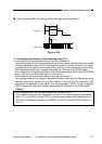
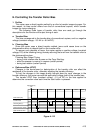
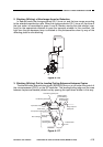
2. Turning On and Off the Transfer Roller Bias
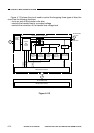
The TFWON signal is generated under the control of the microprocessor (Q512) on
the composite power supply PCB. The signal causes the secondary side of the transfer
transformer (T402) to turn on, thereby applying a DC bias to the transfer roller.
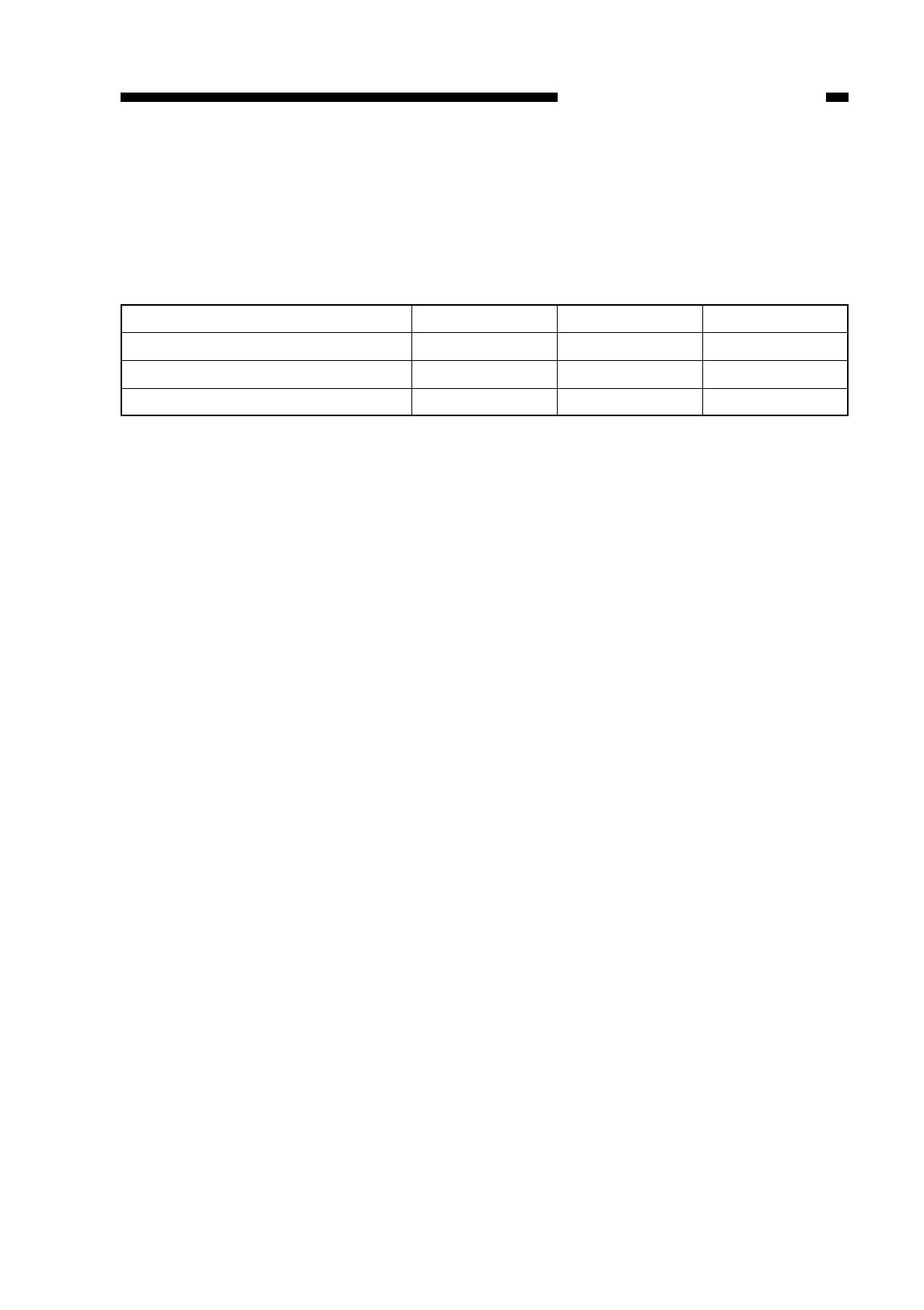
Table 4-102 shows combinations of signals that are used when determining the
transfer roller bias.
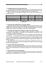
Table 4-102
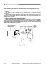
3. Controlling the Transfer Bias to a Constant Voltage
While the transfer DC bias is being generated, the microprocessor (Q512) on the
composite power supply PCB reads the TFWS signal (analog signal) from the constant
voltage control circuit and changes the duty ratio so that the application voltage is
maintained at a constant level, thereby controlling the TFWPWM signal.
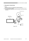
4. Controlling the Transfer Bias Voltage Level Correction (ATVC control)
To correct the changes in the transfer efficiency caused by changes in the
environment or deterioration of the transfer roller, the application voltage level of the
transfer bias is corrected automatically.
A constant current (–10 µA) is let to flow during initial rotation after a press on the
Copy Start key. The microprocessor (Q512) on the composite power supply PCB takes
in the transfer roller application voltage at the time from the constant voltage control
circuit, and sends the data to the microprocessor (Q512) on the DC controller; the DC
controller, in turn, determines the level of the voltage to be applied to the transfer roller
based on the data.
This control is executed only once during initial rotation immediately after a press on
the Copy Start button; for this reason, the application voltage will never vary during
continuous copying operation.
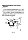
5. Current Limiter Circuit (transfer bias)
Should an overcurrent flow to the secondary side of the transformer (T402) while a
transfer bias is being generated because of changes in the environment, the current
limiter circuit exerts control so as to prevent any occurrence of a current which is 50 µA
or more.
6. Current Limiter Circuit (cleaning bias)
Should an overcurrent flow to the secondary side of the transformer (T402) while a
transfer bias is being generated, the current limiter circuit exerts control to prevent any
occurrence of a current which is 10 µA or more.
COPYRIGHT
©
1997 CANON INC. CANON NP6218 REV. 0 MAY 1997 PRINTED IN JAPAN (IMPRIME AU JAPON)
CHAPTER 4 IMAGE FORMATION SYSTEM
4-15
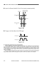
Transfer bias output
Cleaning bias output
Reference bias output (A TVC)
TREVON*
OFF
ON
OFF
TFWON*
ON
OFF
ON
TFWPWM
ON
OFF
OFF