


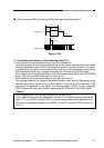
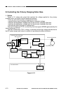
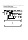
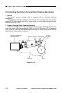

Figure 4-113 shows the circuit used to control the foregoing three types of bias; the
circuit has the following functions:
• turns on and off the transfer roller bias
• controls the transfer bias to a constant voltage
• controls the correction of the transfer bias voltage level
Figure 4-113
COPYRIGHT
©
1997 CANON INC. CANON NP6218 REV. 0 MAY 1997 PRINTED IN JAPAN (IMPRIME AU JAPON)
CHAPTER 4 IMAGE FORMATION SYSTEM
4-14
DC power
supply
assembly
24V
Transfer
bias
control
circuit
Composite power supply PCB
Photosensitive
drum
Transfer roller
Transformer
circuit
24V
T402
TFWON*
TFWPWM
TFWS
TREVON*
Constant
voltage control
circuit
Current
limiter circuit
(transfer bias)
Constant
current circuit
(ATVC)
Current
limiter circuit
(cleaning)
Cleaning bias
control circuit
Microprocessor (Q512)
DC controller PCB
Microprocessor (Q301)