


Implementing OSPF on Cisco IOS XR Software
Information About Implementing OSPF on Cisco IOS XR Software
RC-134
Cisco IOS XR Routing Configuration Guide
Routers
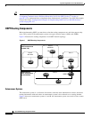
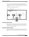
The OSPF network is composed of ABRs, ASBRs, and interior routers.
Area Border Routers (ABR)
ABRs are routers with multiple interfaces that connect directly to networks in two or more areas. An
ABR runs a separate copy of the OSPF algorithm and maintains separate routing data for each area that
is attached to, including the backbone area. ABRs also send configuration summaries for their attached
areas to the backbone area, which then distributes this information to other OSPF areas in the
autonomous system. In Figure 6, there are two ABRs. ABR 1 interfaces Area 1 to the backbone area.
ABR 2 interfaces the backbone Area 0 to Area 2, a stub area.
Autonomous System Boundary Routers (ASBR)
ASBRs provide connectivity from one autonomous system to another system. ASBRs exchange their
autonomous system routing information with boundary routers in other autonomous systems. Every
router inside an autonomous system knows how to reach the boundary routers for its autonomous
system.
ASBRs can import external routing information from other protocols like BGP and redistribute them as
AS-external (ASE) Type 5 LSAs to the OSPF network. If the Cisco IOS XR router is an ASBR, you can
configure it to advertise VIP addresses for content as autonomous system external routes. In this way,
ASBRs flood information about external networks to routers within the OSPF network.
ASBR routes can be advertised as a Type 1 or Type 2 ASE. The difference between Type 1 and Type 2
is how the cost is calculated. For a Type 2 ASE, only the external cost (metric) is considered when
multiple paths to the same destination are compared. For a Type 1 ASE, the combination of the external
cost and cost to reach the ASBR is used. Type 2 external cost is the default and is always more costly
than an OSPF route and used only if no OSPF route exists.
Interior Routers
The interior routers (such as R1 in Figure 6) attached to one area (for example, all the interfaces reside
in the same area).
OSPF Process and Router ID
An OSPF process is a logical routing entity running OSPF in a physical router. This logical routing entity
should not be confused with the logical routing feature that allows a system administrator (known as the
Cisco IOS XR Owner) to partition the physical box into separate routers.
A physical router can run multiple OSPF processes, although the only reason to do so would be to
connect two or more OSPF domains. Each process has its own link-state database. The routes in the
routing table are calculated from the link-state database. One OSPF process does not share routes with
another OSPF process unless the routes are redistributed.
Each OSPF process is identified by a router ID. The router ID must be unique across the entire routing
domain. OSPFv2 obtains a router ID from the following sources, in order of decreasing preference:
OSPF attempts to obtain a router ID in the following ways (in order of preference):
• The 32-bit numeric value specified by the OSPF router-id command in router configuration mode.
(This value can be any 32-bit value. It is not restricted to the IPv4 addresses assigned to interfaces
on this router, and need not be a routable IPv4 address.)