


Chapter 5 Input/Output Interfaces
Compaq Deskpro 4000N and 4000S Personal Computers
First Edition – September 1997
5-28
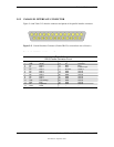
5.6 KEYBOARD/POINTING DEVICE INTERFACE
The keyboard/pointing device interface provides the connection of an enhanced keyboard and a
mouse using PS/2-type connections. The keyboard/pointing device interface function is provided
by the 87307 I/O controller component, which integrates 8042-compatible keyboard controller
logic (hereafter referred to as simply the “8042”) to communicate with the keyboard and pointing
device using bi-directional serial data transfers. The 8042 handles scan code translation and
password lock protection for the keyboard as well as communications with the pointing device.
This section describes the interface itself. The keyboard is discussed in the Appendix C.
5.6.1 KEYBOARD INTERFACE OPERATION
The data/clock link between the 8042 and the keyboard is uni-directional for Keyboard Mode 1
and bi-directional for Keyboard Modes 2 and 3. (These modes are discussed in detail in
Appendix C). This section describes Mode 2 (the default) mode of operation.
Communication between the keyboard and the 8042 consists of commands (originated by either
the keyboard or the 8042) and scan codes from the keyboard. A command can request an action
or indicate status. The keyboard interface uses IRQ1 to get the attention of the CPU.
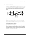
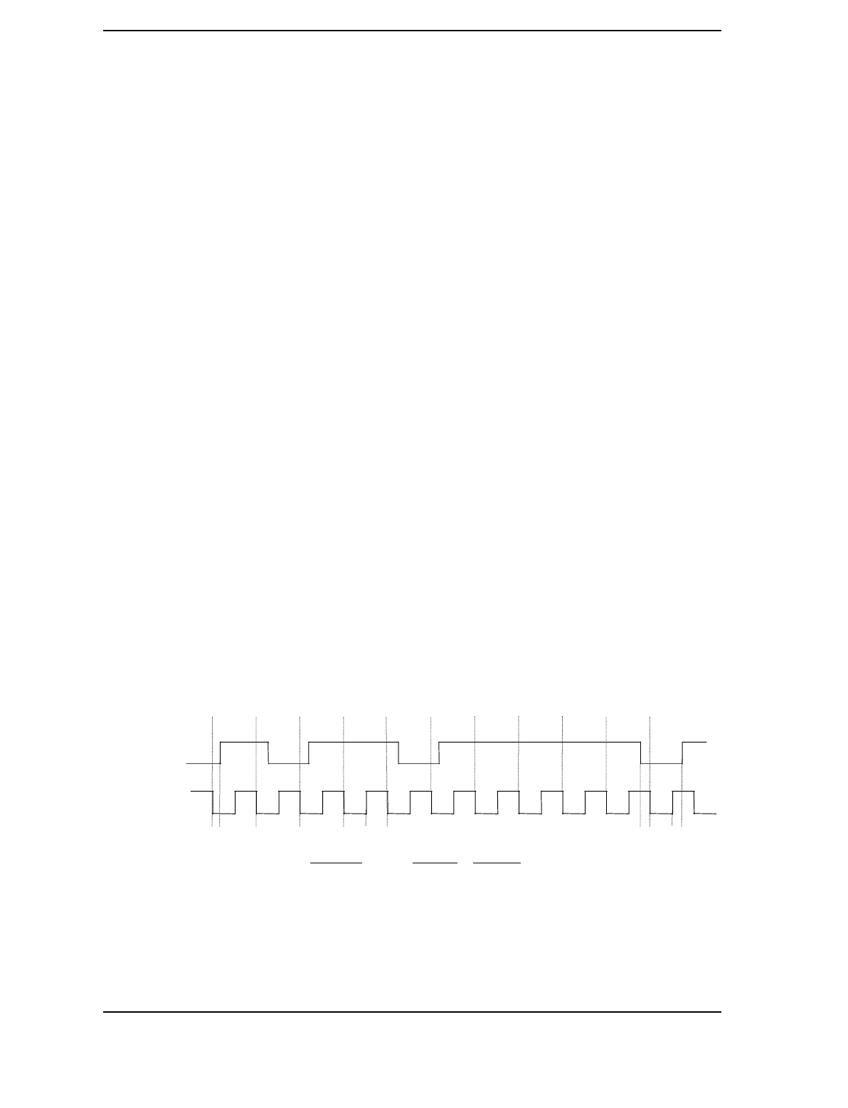
The 8042 can send a command to the keyboard at any time. When the 8042 wants to send a
command, the 8042 clamps the clock signal from the keyboard for a minimum of 60 us. If the
keyboard is transmitting data at that time, the transmission is allowed to finish. When the 8042 is
ready to transmit to the keyboard, the 8042 pulls the data line low, causing the keyboard to
respond by pulling the clock line low as well, allowing the start bit to be clocked out of the 8042.
The data is then transferred serially, LSb first, to the keyboard (Figure 5-5). An odd parity bit is
sent following the eighth data bit. After the parity bit is received, the keyboard pulls the data line
low and clocks this condition to the 8042. When the keyboard receives the stop bit, the clock line
is pulled low to inhibit the keyboard and allow it to process the data.
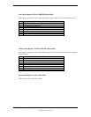
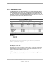
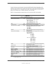
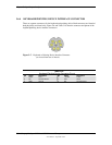
Parameter Minimum
Maximum
Tcy (Cycle Time) 0 us 80 us
Tcl (Clock Low) 25 us 35 us
Tch (clock High) 25 us 45 us
Th (Data Hold) 0 us 25 us
Tss (Stop Bit Setup) 8 us 20 us
Tsh (Stop Bit Hold) 15 us 25 us
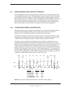
Figure 5–6.
8042-To-Keyboard Transmission of Code EDh, Timing Diagram
Start
Bit
D0
(LSb)
D1 D2 D3 D4 D5 D6
D7
(MSb)
Parity
Stop
Bit
01011011110
Data
Clock
Th
Tcl TchTcy Tss Tsh