


Technical Reference Guide
Compaq Deskpro 4000N and 4000S Personal Computers
First Edition - September1997
4-13
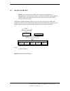
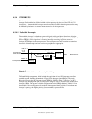
4.3.2 ISA BUS TRANSACTIONS
The ISA bus supports 8- and 16-bit transfers at an 8-MHz rate. Devices limited to 8-bit transfers
use the lower byte portion (data lines 7..0) while 16-bit transfers use the full bandwidth (data
lines 15..0). Addressing is handled by two classifications of address signals: latched and
latchable. Latched address signals ( SA19..0) select the specific byte within the 1-MB section of
memory defined by address lines LA23..17. Latchable address lines (LA23..17) provide a longer
setup time for pre-chip selection or for pre-address decoding for high-speed memory and allow
access to up to 16-MB of physical memory on the ISA bus. The SA19..17 signals have the same
values as the LA19..17 signals for all memory cycles. The I/O cycles use only the SA15..0
signals.
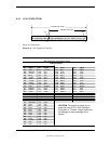
The key control signals are described as follows:
♦ MRDC- (Memory Read Cycle): MRDC- is active on all ISA memory reads accessing
memory from 000000h to FFFFFFh.
♦ SMEMR- (System Memory Read): SMEMR- is asserted by the PCI/ISA bridge to request an
ISA memory device to drive data onto the data lines for accesses below one megabyte.
SMEMR- is a delayed version of MRDC-.
♦ MWTC- (Memory Write Cycle): MWTC- is active on all ISA memory write cycles accessing
memory from 000000h to FFFFFFh.
♦ SMEMW- (System Memory Write): SMEMW- is asserted by the PCI/ISA bridge to request
an ISA memory device to accept data from the data lines for access below one megabyte.
SMEMW- is a delayed version of MWTC-.
♦ IORC- (Input/Output Read Cycle): IORC- commands an ISA I/O device to drive data onto
the data lines.
♦ IOWC- (Input/Output Write Cycle): IOWC- commands an ISA I/O device to accept data
from the data lines.
♦ SBHE- (System Byte High Enable): SBHE- indicates that a byte is being transferred on the
upper half (D15..8) of the data lines.
♦ SA0- (System Address Bit <0>): This bit is the complement of SBHE- and indicates that a
byte is being transferred on the lower half (D7..0) of the data lines.
♦ M16- (16-bit Memory Cycle): M16- is asserted by 16-bit ISA devices to indicate 16-bit
memory cycle capability.
♦ IO16- (16-bit I/O Cycle): IO16- is asserted by 16-bit ISA devices to indicate 16-bit I/O cycle
transfer capability.
If the address on the SA lines is above one megabyte, SMRDC- and SMWTC- will not be active.
The MRDC- and MWTC- signals are active for memory accesses up to 16 megabytes and can be
used by any device that uses the full 16-bit ISA bus. To request a 16-bit transfer, a device asserts
either the M16- (memory) or IO16- (I/O) signal when the device is addressed.
When another device (such as a DMA device or another bus master) takes control of the ISA, the
Bus Address Latch Enable (BALE) signal is held active for the duration of the operation. As a
result , signals LA23..17 are always enabled and must be held stable for the duration of each bus
cycle.
When the address changes, devices on the bus may decode the latchable address (LA23..17) lines
and then latch them. This arrangement allows devices to decode chip selects and M16- before the
next cycle actually begins.