


Chapter 3 Processor/Memory Subsystem
Compaq Deskpro 4000N and 4000S Personal Computers
First Edition - September 1997
3-4
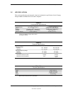
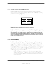
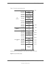
3.2.2 BUS/PROCESSING SPEED SELECT
The Pentium MMX-based system board includes a four-position DIP switch (SW1) that is used to
select the Host bus frequency and the processing frequency of the system. The SW1 positions 2
and 3 control the Bus Fraction (BF0, BF1) signals to the CPU, which determines the bus-to-core
speed ratio. Position 5 of SW1 determines the bus frequency generated by the clock generator
(refer to Chapter 4, “System Support” for more information on clock frequency generation).
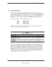
Table 3-2 shows the switch configurations to be used with a particular microprocessor.
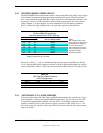
Table 3–2.
Pentium MMX Microprocessor Bus/Core Speed Switch Settings
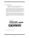
Table 3-2.
Pentium MMX Microprocessor
Bus/Core Speed Switch (SW1) Settings
235
Microprocessor
Bus/Core Speed (in MHz)
Off Off Off 60/210
Off Off On 66/233
Off On Off 60/180
Off On On 66/200
On Off Off 60/120
On Off On 66/133
On On Off 60/150
On On On 66/166
NOTES:
Shipping configurations are unshaded
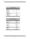
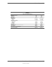
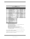
The status of SW1-2, -3, and -5 is readable through general-purpose I/O (GPIO) port 78h bits
<2..0>, allowing BIOS and/or diagnostic software to check an installed microprocessor with the
switch configuration. Table 3-3 shows the switch position-to-GPIO-to-I/O port 78h input wiring.
Table 3–3
. SW1 Bus/Core Speed Positions to GPIO Assignments
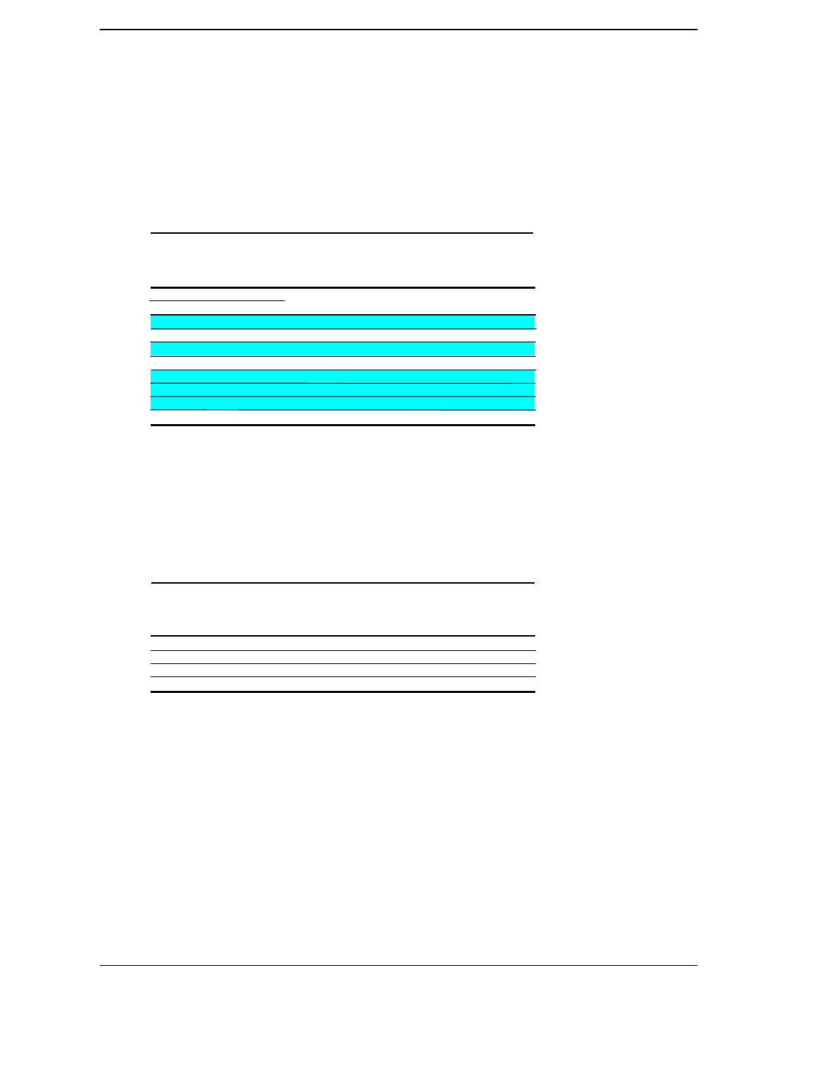
Table 3-3.
SW1 Bus/Core Speed Positions
to GPIO Assignments
Switch Position Signal Name GPIO Number I/O Port 78h
SW1-2 BF0 10 bit <0>
SW1-3 BF1 11 bit <1>
SW1-5 SPD66- 12 bit <2>
SPD = Bus frequency select BF = Bus/core fraction
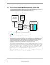
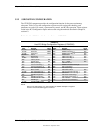
3.2.3 SECONDARY (L2) CACHE MEMORY
The system board comes with 256 kilobytes of SRAM implemented as the secondary (L2) cache
to the integrated L1 cache of the Pentium MMX microprocessor. This L2 cache uses two 32K x
32 synchronous pipelined burst SRAMs (with one 32K x 8 TAG RAM) arranged as a direct-
mapped, write-back. The L2 cache provides a typical cycle time (in Host clocks) of 3-1-1-1 for
burst reads (cache hit) and writes (write back). The L2 controller allows the full system memory
range to be cached.
DIP SW1 Settings [1]
NOTE:
SW1 should be set to match
the specified core speed of the
microprocessor. Configuring
for a core speed lower or
higher than that for which the
CPU is designed can result in
unstable or possibly
destructive operation.