


Chapter 7 Power and Signal Distribution
Compaq Deskpro 4000N and 4000S Personal Computers
First Edition - September 1997
7-4
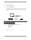
7.3 POWER DISTRIBUTION
7.3.1 3.5/5/12 VDC DISTRIBUTION
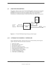
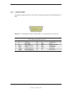
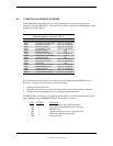
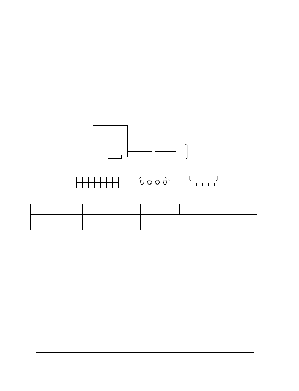
The power supply assembly includes a connector (P1) that mates directly with the system board
connector (P17) when the assembly is installed. The power supply assembly also includes a cable
assembly that routes +3.5 VDC, +5 VDC, -5 VDC, +12 VC, and -12 VDC to the individual drive
assemblies.
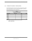
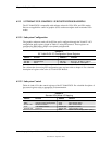
Connector Pin 1 Pin 2 Pin 3 Pin 4 Pin 5 Pin 6 Pin 7 Pin 8 Pin 9 Pin 10
P1 +3.5 +3.5RS RTN +5 RTN +5 RTN +3.5 -12 FO
P1 [2] PS On +5AUX RS rtn +12 RTN RSRTN RTN -5 +5 +5
P2 +5 GND GND +12
P3 +12 GND GND +5
NOTES:
[1] Connector P1 mates directly with connector P17 on the system board.
[2] This row represents pins 11-14 of connector P1.
All + and - values are VDC
.
RTN = Return (signal ground)
GND = Power ground
RS = Remote sense
FO = Fan off
Figure 7–2
. Power Cable Diagram
Power Supply
Assembly
Drive
Assemblies
P1
[
1
]
P3 P2
1 2 3 4
P3
P2
4 3 2 1
P1
1
1211
2 5 4 3 7
8
6
9 1410 13