


Technical Reference Guide
Compaq Deskpro 4000N and 4000S Personal Computers
First Edition - September 1997
5-9
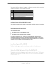
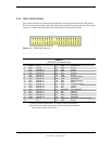
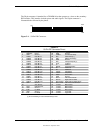
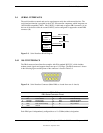
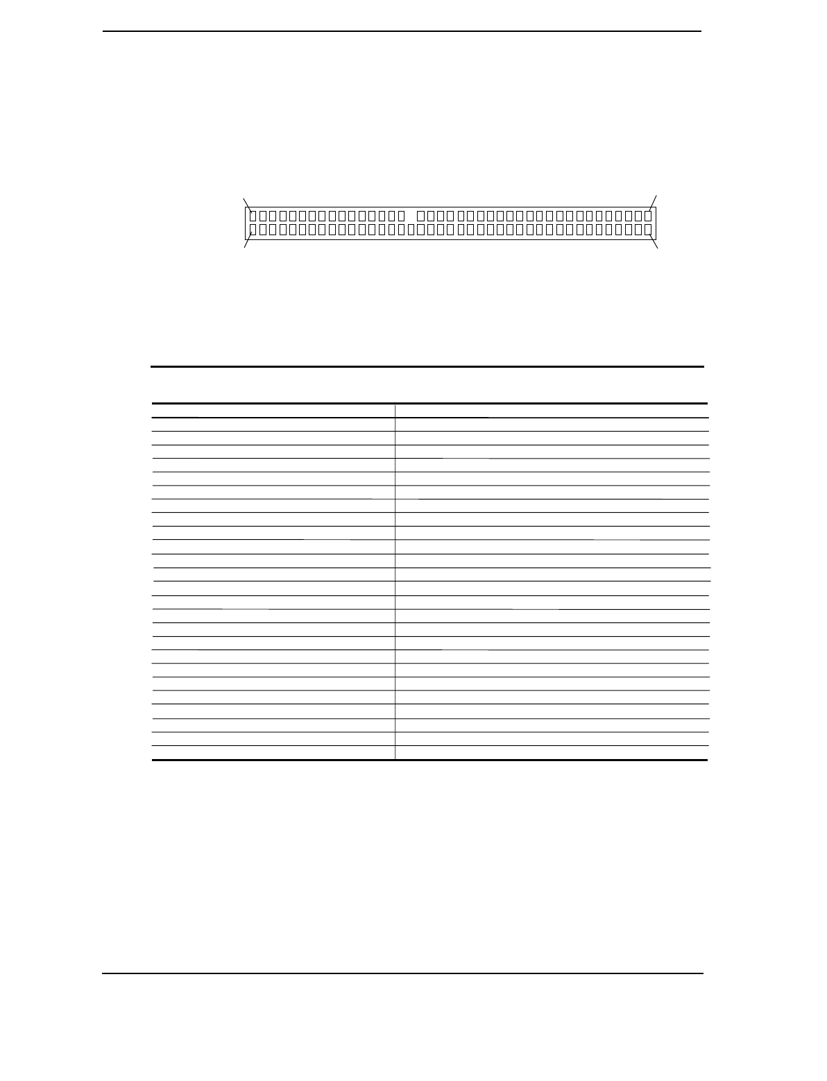
The 50-pin connector is intended for a CD-ROM drive that operates as a slave on the secondary
IDE interface. This interface includes power and audio signals. The 50-pin connector is
illustrated below followed by the pinout.
Figure 5–1. 50-Pin IDE Connector.
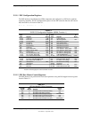
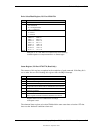
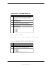
Table 5–6. 40-Pin IDE Connector Pinout
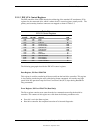
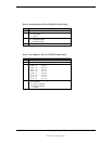
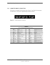
Table 5-5.
50-Pin IDE Connector Pinout
Pin Signal Description Pin Signal Description
1 RESDRV- Reset 26 GND Ground
2 GND Ground 27 CHRDY I/O Channel Ready
3 SHD07 Data Bit <7> 28 ALE Cable Select [1]
4 SHD08 Data Bit <8> 29 DAK- DMA Acknowledge
5 SHD06 Data Bit <6> 30 GND Ground
6 SHD09 Data Bit <9> 31 IRQ Interrupt Request [1]
7 SHD05 Data Bit <5> 32 IO16- 16-bit I/O
8 SHD10 Data Bit <10> 33 A1 Address 1
9 SHD04 Data Bit <4> 34 PDIAG- Pass Diagnostics
10 SHD11 Data Bit <11> 35 A0 Address 0
11 SHD03 Data Bit <3> 36 A2 Address 2
12 SHD12 Data Bit <12> 37 CS1FX- Chip Select
13 SHD02 Data Bit <2> 38 CS3FX- Chip Select
14 SHD13 Data Bit <13> 39 DASF- Drive Active
15 SHD01 Data Bit <1> 40 GND Ground
16 SHD14 Data Bit <14> 41 AUD L Left Channel Audio
17 SHD00 Data Bit <0> 42 AUD R Right Channel Audio
18 SHD15 Data Bit <15> 43 AUD R RTN Right Channel Audio Return
19 GND Ground 44 AUD L RTN Left Channel Audio Return
20 -- (Key Space) 45 +5 VDC Motor Power
21 DRQ DMA Request 46 +5 VDC Motor Power
22 GND Ground 47 +5 VDC Motor Power
23 IOW- I/O Write 48 +5 VDC Motor Power
24 GND Ground 49 +5 VDC Log Power
25 IOR- I/O Read 50 +5 VDC Log Power
NOTES:
[1] Pin is left floating to make CD-ROM always slave.
P1
P49
P50
P2