


Technical Reference Guide
Compaq Deskpro 4000N and 4000S Personal Computers
First Edition - September1997
4-19
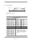
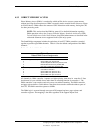
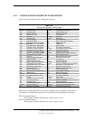
Table 4–11. Maskable Interrupt Priorities and Assignments
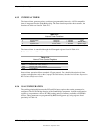
Table 4-11.
Maskable Interrupt Priorities and Assignments
Priority Signal Label Source (Typical) Notes
1 IRQ0 Interval timer 1, counter 0
2 IRQ1 Keyboard
3 IRQ8- Real-time clock
4 IRQ9 Spare and ISA connector pin B04
5 IRQ10 Spare and ISA connector pin D03
6 IRQ11 Spare and ISA connector pin D04
7 IRQ12 Mouse and ISA connector pin D05
8 IRQ13 Coprocessor (math)
9 IRQ14 IDE primary I/F and ISA connector pin D07
10 IRQ15 IDE secondary I/F and ISA connector pin D06
11 IRQ3 Serial port (COM2) and ISA connector pin B25
12 IRQ4 Serial port (COM1) and ISA connector pin B24
13 IRQ5 Audio subsystem and ISA connector pin B23
14 IRQ6 Diskette drive controller and ISA connector pin B22
15 IRQ7 Parallel port (LPT1)
-- IRQ2 NOT AVAILABLE (Cascade from interrupt controller 2)
NOTE:
[3] Alternate available interrupts: IRQ5, 9,10,11,14, or 15
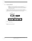
Interrupts generated by PCI devices can be configured to share the standard AT (IRQn) interrupt
lines. Refer to section 4.2.5 “PCI Interrupt Mapping” for information on PCI interrupts.
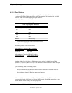
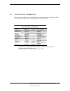
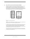
Maskable Interrupt processing is controlled and monitored through standard AT-type I/O-
mapped registers. These registers are listed in Table 4-12.
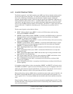
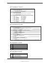
Table 4–12. Maskable Interrupt Control Registers
Table 4-12.
Maskable Interrupt Control Registers
I/O Port Register
020h Base Address, Int. Cntlr. 1
021h Initialization Command Word 2-4, Int. Cntlr. 1
0A0h Base Address, Int. Cntlr. 2
0A1h Initialization Command Word 2-4, Int. Cntlr. 2
The initialization and operation of the interrupt control registers follows standard AT-type
protocol.