


Chapter 4 System Support
Compaq Deskpro 4000N and 4000S Personal Computers
First Edition - September 1997
4-42
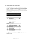
4.6.2 87307 I/O CONTROLLER CONFIGURATION
The 87307 I/O controller contains various functions such as the keyboard/mouse interfaces,
diskette interface, serial interfaces, and parallel interface. Software control of these interfaces
uses standard AT-type I/O addressing. Firmware configuration of these functions uses indexed
ports unique to the 87307. In this system, hardware strapping selects I/O addresses 015Ch and
015Dh at reset as the Index/Data ports for accessing the configuration registers of the logical
devices within the 87307. The hardware strapping also places the 87307 into PnP motherboard
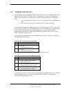
mode. Table 4-18 lists the PnP standard configuration registers for the devices within the 87307.
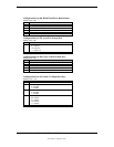
Table 4–18.
87307 I/O Controller PnP Standard Control Registers
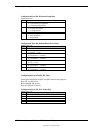
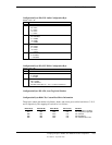
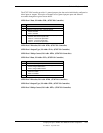
Table 4-18.
87307 I/O Controller PnP Standard Configuration Registers
Index Function Reset Value
00h Set RD_DATA Port 00h
01h Serial Isolation
02h Configuration Control
03h Wake (CSN) 00h
04h Resource Data
05h Status
06h Card Select Number (CSN) 00h
07h Logical Device Select:
00h = 8042 Controller (Keyboard I/F)
01h = 8042 Controller (Mouse I/F)
02h = RTC/APC Configuration
03h = Diskette Controller
04h = Parallel Port
05h = UART 2 (Serial Port B / IrDA)
06h = UART 1 (Serial Port A)
07h = GPIO Ports
08h = Power Management
00h
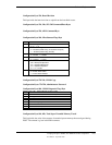
20h Super I/O ID Register (SID) A0h
21h SIO Configuration 1 Register D6h
22h SIO Configuration 1 Register 02h
23h Programmable Chip Select Configuration Index 00h
24h Programmable Chip Select Configuration Data 00h
30h Logical Device Activate --
31h Logical Device I/O Range Check --
60,61h Logical Device Data Base Address --
62,63h Logical Device Command Base Address --
70h Logical Device Interrupt Select --
71h Logical Device Interrupt Type --
74,75h Logical Device DMA Assignment --
F0h Logical Device Configuration --
F1h Drive ID (Logical Device 03 only) --
The configuration registers are accessed by writing the appropriate logical device’s number to
index 07h and writing the desired offset to the index register. The data is then either written to or
read from the data register.