Technical Reference Guide
Compaq Deskpro 4000N and 4000S Personal Computers
First Edition - September 1997
5-3
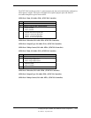
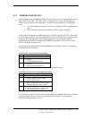
5.2.1.3 IDE ATA Control Registers
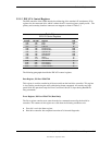
The IDE controller of the 82586 decodes the addressing of the standard AT attachment (ATA)
registers for the connected drive, which is where the ATA control registers actually reside. The
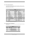
primary and secondary interface connectors are mapped as shown in Table 5-3.
Table 5–3.
IDE ATA Control Registers
Table 5-3.
IDE ATA Control Registers
Primary
I/O Addr.
Secondary
I/O Addr. Register R/W
1F0h 170h Data R/W
1F1h 171h Error R
1F1h 171h Features W
1F2h 172h Sector Count R/W
1F3h 173h Sector Number R/W
1F4h 174h Cylinder Low R/W
1F5h 175h Cylinder High R/W
1F6h 176h Drive/Head R/W
1F7h 177h Status R
1F7h 177h Command W
3F6h 376h Alternate Status R
3F6h 376h Drive Control W
3F7h 377h Drive Address R
3F7h 377h n/a for hard drive W
The following paragraphs describe the IDE ATA control registers.
Data Register, I/O Port 1F0h/170h
This register is used for transferring all data to and from the hard drive controller. This register
is also used for transferring the sector table during format commands. All transfers are high-
speed 16-bit I/O operation except for Error Correction Code (ECC) bytes during Read/Write
Long commands.
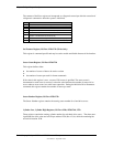
Error Register, I/O Port 1F1h/171h (Read Only)
The Error register contains error status from the last command executed by the hard drive
controller. The contents of this register are valid when the following conditions exist:
♦
Error bit is set in the Status register
♦
Hard drive controller has completed execution of its internal diagnostics


