


System
Configuration
S900II
IV – V
ariable addr
essing
23
01T01350_0
2.2.98
IV – V
ARIABLE
ADDRESSING
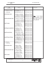
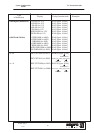
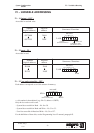
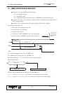
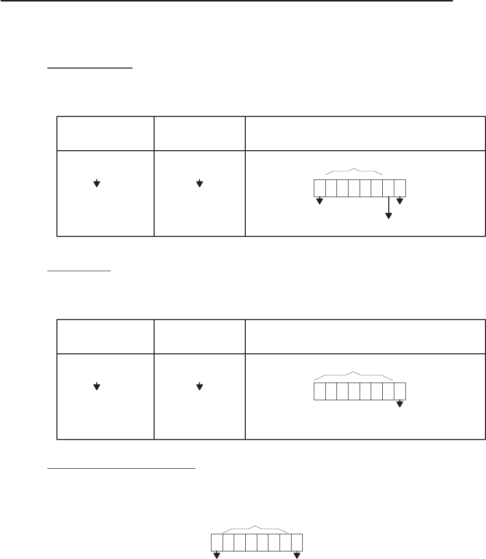
IV – 1. Output – OUT –
Accessible in read and write.
Number
(logical address)
Physical
address
Structures / Functions
OUT 000
OUT 255
28A0
299F
2 A1D
OUT
125
not used
Forcing
(Extended monitor)
Continuous status
(See Param. No 14)
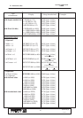
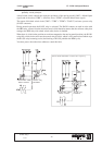
IV – 2. Input – IN –
Accessible in read.
IN 000
IN 255
29A0
2A9F
2 9AB
IN
01
1
not used
Number
(logical address)
Physical
address
Structures / Functions
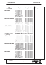
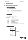
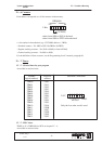
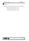
IV – 3. User and system bits – BIT –
Each address corresponds to an 8 bit structure in memory.
0281x
BIT 0
not used
Forcing
(Extended monitor)
x = bit number in hexadecimal (e.g.: Bit 31, address = 0282F).
Only the low order word is used.
– System bits accessible in Read – No. 0 to 30.
– System bits accessible in Read and Write – No. 31 to 33.
– User bits accessible in Read and Write – No. 34 to 127.
For the definition of these bits, see the Programming Level 2 manual, paragraph I3.