System
Configuration
S900II
V – CPU fault signalling
26
01T01350_0
2.2.98
V – CPU
F
AUL
T SIGNALLING
V – 1. Flashing
Leds
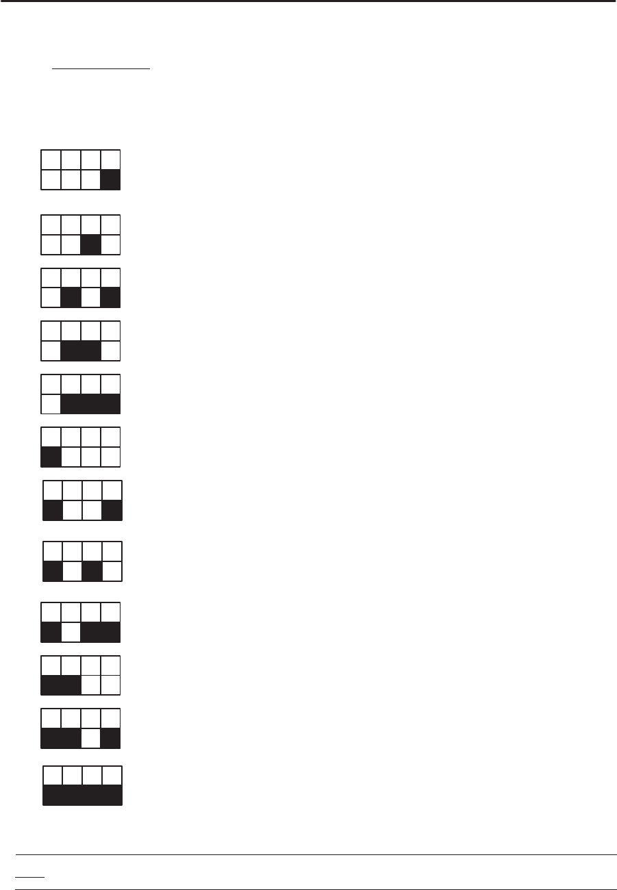
These signal a CAN network fault by displaying the problem number in binary on the LEDs at the
bottom of the CPU, and the node number (if concerned) on the LEDs at the top if the pendant is not
functioning.
30
1 = CAN driver initialization fault
2 = Write problem in Flashprom
5 = A double (or more) node on the network (code + node)
6 = Problem during the CONNECTION phase (code + node)
7 = Problem during the PREPARATION phase (code + node)
8 = Problem during the START phase (code + node)
9
= The network does not correspond to the parametered configuration (code + node)
10 = “Node–guarding” problem (code + node). Communication fault with the pendant ;
this
may be due to the CAN speed being too great for the length of the cable used,
or a bad
line adaptation, or interference, etc.
11 = CPU emission problem
12 = CPU reception problem
13 = Topology fault of the remote I/O
15
= EMERGENCY message received (code + node). Problem on the pendant or with
communication between the pendant and the CPU (see 10)
Note : In the event of a NODE GUARDING fault, fault 15 may appear alternately with fault 10.


