


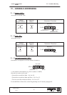
System
Configuration
S900II
VI – IMM Anticipated Restart
29
01T01350_0
2.2.98
"
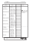
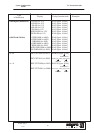
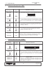
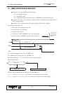
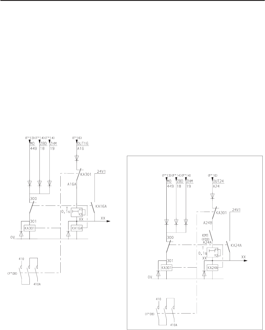
Safety circuit principle.
A hard–wired circuit controls the respective positions of the moving mould (“MO” = Mould Open
signal) and of the robot (“ZBD” = Arm Free Area / “ZHM” = Outside Mould Area signal).
The
output of this
hard–wired circuit (”MO” + ”ZBD” + ”ZHM” = ”KA301”) activates a power relay
(KA301 contactor).
During normal operation, the KA301 relay is activated. The KA301 contacts are used in series with
the SBD relay contact from the interface board, which therefore means that the software safety that
manages the SBD relay with a hard–wired safety device is doubled.
When
there
is a fault (robot position not conform compared to the moving mould position), the KA301
relay falls, which
in turn activates the control relay KA16A, which is self–powered and which stops
the KA301 relay becoming active (the blocking of KA301 prohibits the IMM cycle).
You must power down the robot cabinet to cancel this fault.
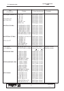
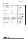
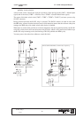
“KA301” relay
CONTROL
ANCILLARY “ARM
FREE” SAFETY
FOR 32 OUTPUT BOARDS : as OUTxx active at power up
“KA301” relay
CONTROL
ANCILLARY “ARM
FREE” SAFETY