


System
Configuration
S900II
IV – V
ariable addr
essing
25
01T01350_0
2.2.98
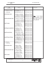
IV – 6. Counters
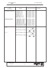
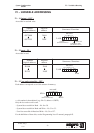
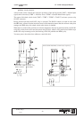
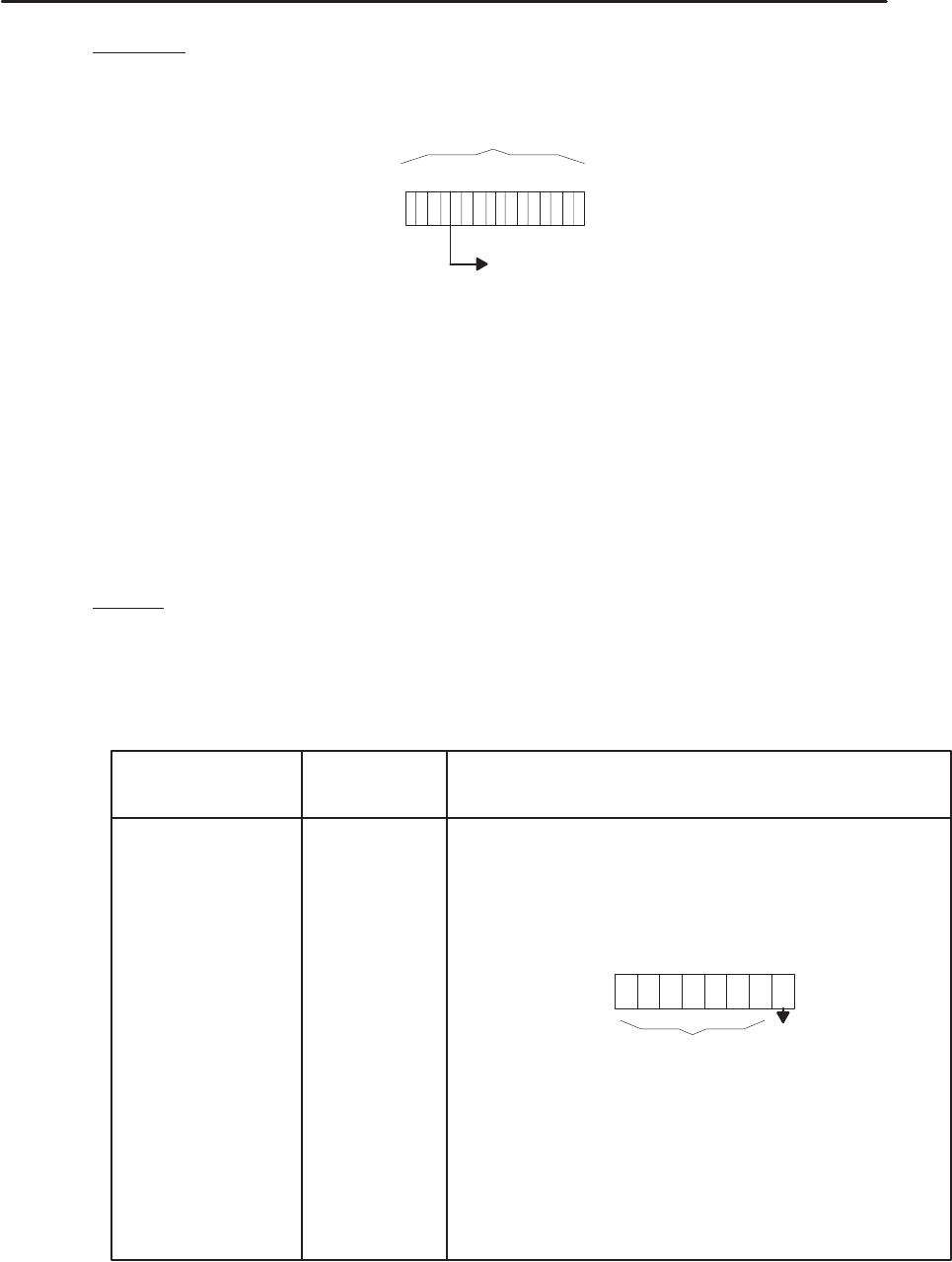
Each address corresponds to a 16 bit structure in the memory.
2 B4x
CNT0008
WRD0088
. values from 0000 to 9999 in decimal
. values from 0000 to FFFF in hexadecimal
b15 b0
x = bit number in hexadecimal (e.g.: CNT 0008, address = 2 B50).
– Standard counters – No. 0000 to 0015 (0x2B40 to 0x2B5E).
– Regular stacking counters – No. 0041 to 9960 (as from 0x2 B60).
– General stacking counters – No 0061 to 9980.
For the definition of these counters, see the Programming Level 2 manual, paragraph I6.
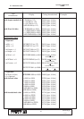
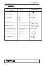
IV – 7. Timers
IV – 7. 1.End of timer for part program
Accessible in read and write.
TIM00 2 890
TIM01 2 891
TIM02 2 892
TIM03 2 893
TIM04 2 894
TIM05 2 895
TIM06 2 896
TIM07 2 897
TIM08 2 898
TIM09 2 899
TIM10 2 89A
TIM11 2 89B
TIM12 2 89C
TIM13 2 89D
TIM14 2 89E
TIM15 2 89F
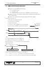
2 897
TIM07
not used
Only the low order word is used
Number
(logical address)
Physical
address
Structures / Functions
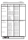
IV – 7. 2.PLC timer
TIM00 to 15 = WRD 0064 to 0079 see chapter IV – 4.
Accessible in read and write.