


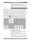

FlipTop Computer Center Crestron QM-FTCC
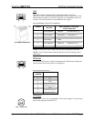
Ethernet
8
1
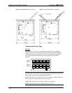
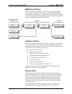
An 8-pin RJ-45 port is used for connection to the Ethernet, providing local area
network or Web access (cable is not supplied). Refer to the following table for
the Ethernet connector signals and use an appropriate cable.
Ethernet Connector Pinout
PIN SIGNALS
1 TX + passthrough
2 TX - passthrough
3 RC+ passthrough
4 passthrough
5 passthrough
6 RC - passthrough
7 passthrough
8 passthrough
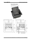
Ports (Underside)
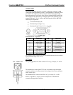
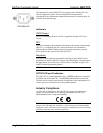
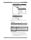
MIC 1 / MIC 2
These two 5-pin 3.5 mm detachable terminal blocks provide two microphone
and line level audio inputs.
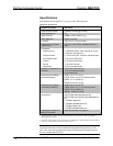
• Balanced microphone input level: -60 to –20 dBV nominal
• Balanced line input level: -28 to +12 dBV, 4 V
RMS
maximum
• Unbalanced input level: -34 to +6 dBV, 2 V
RMS
maximum
• Microphone input impedance: 10 kΩ,
accepts balanced microphones 60 to 600 Ω
• Line input impedance: 22 kΩ (balanced), 11 kΩ (unbalanced)
• Phantom power: 10 mA (total) at 48 VDC, software enabled for both
inputs
• Mic level indicators (via software): 20 dB below clipping (Norm), 6 dB
below clipping (Overload)
• Mic Input Gain: 0 to 100% (0 to 40 dB) plus mute
• Gate level (threshold): 0 to 100%
• Attack: 1 to 100 ms
• Decay (release): 1 to 5000 ms
• Analog to Digital conversion: 24-bit, 48 kHz
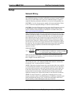
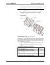
NET (x2)
NET
24 Y Z G
NET
24 Y Z G
These two 4-pin terminal block connectors, located on the bottom side of the
QM-FTCC, are for connection to the Cresnet network. One connector is used
to connect to the Cresnet network while the second connector can be used to
connect another Cresnet device. Cresnet power to the QM-FTCC is supplied
through either of these connectors. For more information, refer to “Network
Wiring” on page 13.
10 • FlipTop Computer Center: QM-FTCC Operations & Installation Guide - DOC. 6313A