


Crestron QM-FTCC FlipTop Computer Center
Setup
Network Wiring
CAUTION: In order to ensure optimum performance over the full range of
your installation topology, Crestron Certified Wire, and only Crestron Certified
Wire, may be used. Failure to do so may incur additional charges if support is
required to identify performance deficiencies as a result of using improper wire.
CAUTION: Use only Crestron power supplies for Crestron equipment. Failure
to do so could cause equipment damage or void the Crestron warranty.
CAUTION: Provide sufficient power to the system. Insufficient power can lead
to unpredictable results or damage to the equipment. Please use the Crestron
Power Calculator to help calculate how much power is needed for the system
(http://www.crestron.com/calculators
).
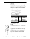
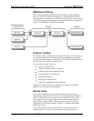
When calculating the length of wire for a particular Cresnet run, the wire gauge
and the Cresnet power usage of each network unit to be connected must be taken
into consideration. Use Crestron Certified Wire only. If Cresnet units are to be
daisy-chained on the run, the Cresnet power usage of each network unit to be
daisy-chained must be added together to determine the Cresnet power usage of
the entire chain. If the unit is a home-run from a Crestron system power supply
network port, the Cresnet power usage of that unit is the Cresnet power usage of
the entire run. The wire gauge and the Cresnet power usage of the run should be
used in the following equation to calculate the cable length value on the
equation’s left side.
Cable Length Equation
40,000
Where:
R x P
L <
L = Length of run (or chain) in feet.
R = 6 Ohms (Crestron Certified Wire: 18 AWG (0.75 MM
2
))
P = Cresnet power usage of entire run (or chain).
Make sure the cable length value is less than the value calculated on the right
side of the equation. For example, a Cresnet run drawing 20 watts should not
have a length of run more than 333 feet.
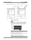
NOTE: All Crestron certified Cresnet wiring must consist of two twisted pairs.
One twisted pair is the +24V conductor and the GND conductor, and the other
twisted pair is the Y conductor and the Z conductor.
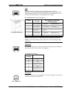
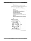
NOTE: When daisy-chaining Cresnet units, strip the ends of the wires carefully
to avoid nicking the conductors. Twist together the ends of the wires that share a
pin on the network connector, and tin the twisted connection. Apply solder only
to the ends of the twisted wires. Avoid tinning too far up the wires or the end
becomes brittle. Insert the tinned connection into the Cresnet connector and
tighten the retaining screw. Repeat the procedure for the other three conductors.
NOTE: For larger networks (i.e., greater than 28 network devices), it may
become necessary to add a Cresnet Hub/Repeater (CNXHUB) to maintain signal
quality throughout the network. Also, for networks with lengthy cable runs, it
may be necessary to add a Hub/Repeater after only 20 devices.
Operations & Installation Guide – DOC. 6313A FlipTop Computer Center: QM-FTCC • 13