


Crestron QM-FTCC FlipTop Computer Center
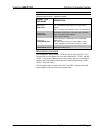
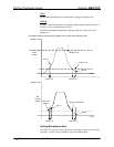
NOTE: <AttackTime> and <DecayTime> are applied to both microphone
inputs.
NOTE: The gating level indicators will still function even if the gating function
is not enabled.
NOTE: Nominal indication is reported at 20 dB below input clip level. Clip
indication is reported at 6 dB below input clip level.
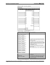
NOTE: Returned values match values that were selected for the
<Mic1GatingLevel>, <Mic2GatingLevel>, <Mic1Gain>, <Mic2Gain>,
<AttackTime> and <DecayTime> inputs.
NOTE: Refer to page 41 for adjustment details of the microphone inputs.
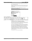
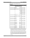
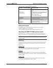
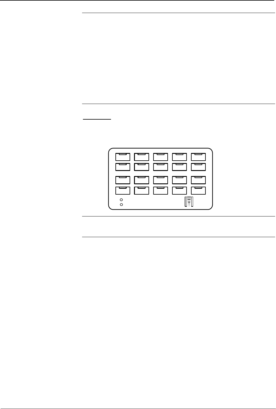
Buttons
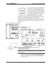
The Buttons module is built into slot 03 of the QM-FTCC. It consists of a
keypad 10 to 20 buttons with LED indicators, and two bar graphs. The button
presses are fixed and map to <press> outputs on the symbol detail, as follows:
Row 1
Row 2
Row 3
Row 4
PWR
NET
12 345
678910
11 12 13 14 15
16 17 18 19 20
NOTE: Numbers in this illustration are for programming purposes only.
NOTE: Not applicable to NB models.
The buttons on rows 1 and 2 can be combined vertically to form one larger
button. For example, the button caps for buttons #1 and #6 can be replaced with
one larger button cap. Similarly, the vertical pairs on rows 3 and 4 can be
combined to form one larger button. For example, buttons #13 and #18 can be
combined. No other combinations are valid. That is, two buttons cannot be
combined horizontally; the buttons on rows 2 and 3 cannot be combined.
Operations & Installation Guide – DOC. 6313A FlipTop Computer Center: QM-FTCC • 39