


Crestron QM-FTCC FlipTop Computer Center
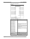
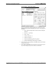
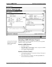
Use the Realtime Mode in SystemBuilder to control phantom power, gain and
gate settings, and to monitor the gate, normal, and clip level indicators. For
information on using SystemBuilder software, refer to the extensive help
information provided with the software.
NOTE: The input gain is independent of the system’s output volume level.
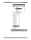
1. To adjust the input gain, set the gain and noise gate to their lowest
settings. Disable the “Mute” function by removing the check from the
Mute checkbox.
2. Connect a microphone and enable phantom power if required.
3. Increase the gain while providing a “normal” sound level input to the
microphone. When the “Norm” indicator shows fairly consistent
activity, you’ve reached a good signal level for the QM-FTCC.
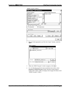
NOTE: The "clip" indicator shows that the signal is clipping. Let your ears be
the judge, but when the clip indicator is active, you are approaching or have
reached distortion in your QM-FTCC signal. Occasional clip indications on loud
input are expected, but constant clip indicator activity is a sign that the gain may
be set too high.
4. Set the system output volume to a desirable listening level and verify
the gain settings by listening to the system output. Some minor gain
adjustment may be required for the “best sound” in any specific
configuration.
Setting the Gating Level
The QM-FTCC provides an input level gating function that will mute a
microphone signal when the input sound level is below a user-set threshold. This
function can be enabled or disabled via software commands.
Use the Realtime Mode in SystemBuilder to control phantom power, gain and
gate settings, and to monitor the gate, normal, and clip level indicators. For
information on using SystemBuilder software, refer to the extensive help
information provided with the software.
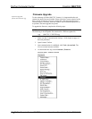
The following procedure sets the optimal “gate level” for the microphone inputs:
1. Follow the “Setting Microphone Gain” procedure on page 42 to set the
gain for each microphone input.
2. Set the noise gate level, attack and decay times to minimum. Disable
the “Mute” function by removing the check from the Mute checkbox.
3. While providing a level to the microphone that is equivalent to the
background noise that should be gated out, increase the noise gate level
until the Gated indicator turns off. When the input sound levels are at
or below the established noise gate level, the microphone output signal
will be gated off.
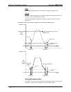
4. Set the “attack time” to the minimum level and the “decay time” to the
maximum level. These settings provide the shortest time to enable the
microphone output when an input is above the gating level, and the
longest time before disabling the microphone after such an input.
NOTE: The “attack” and “decay times” are applied to both microphone inputs.
Operations & Installation Guide – DOC. 6313A FlipTop Computer Center: QM-FTCC • 43