


Chapter 2 - Start-Up Instructions
DCS 500B / DCP 500B Operating Instructions IV A 2 - 1
General notes
CAUTION: it is absolutely essential that the applicable accident prevention
regulations be observed by the user (in this context, please also
read the chapter entitled "Safety Instructions")!
How this chapter is structured
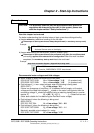
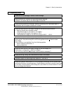
For better understanding the individual steps of start-up work are distinguished by
a) frames
without any additional marking on the left side:
These steps of start-up work must always be performed (= mandatory start-up work)!
Example:
522 = GERMAN [Only with the SDCS-CON-2 control board & the CDP 312 panel!]
Activates German texts on the display ...........
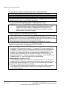
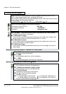
b) frames
with marking on the left side („columns“ shaded in grey):
These steps of start-up work have to be performed only when the condition stated
(as heading) applies to the selected drive configuration!
After this work has been
completed, the
mandatory start-up work has to be continued.
Example:
Only when connection diagram 1 (Appendix A) is being used!
906 = 12502
Function „EMERGENCY STOP“ de-activated ............
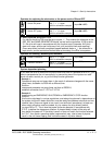
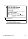
Recommended motor voltages and field voltages
• Motor voltage U
A
when the following units are used
DCS 501B / DCP 501B: U
Amax
= Line voltage * 1.16 (2- quadrant unit)
DCS 502B / DCP 502B: U
Amax
= Line voltage * 1.05 (4- quadrant unit)
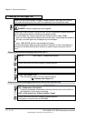
• Field voltage U
F
(= max. output voltage) when the following is being used
SDCS-FEX-1: U
F
= Line voltage * 0.9
If there is a divergence of more than 10 % between the field supply unit's output
voltage and the rated field voltage U
Frated
stated on the motor's rating plate, then the
connecting voltage U
N
should be reduced, using a matching transformer or a series
resistor R
v
: R
v
= (0.9 * U
N
- U
F
) / I
F
I
F
= Rated field current
(Note: also suitable for fine-balancing the maximum motor voltage)
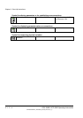
• Field voltage U
F
when the following is being used
SDCS-FEX-2 /
DCF 503 / DCF 504: U
F
= Line voltage * 0.6 ... 0.8
• Field voltage U
F
when the following is being used
DCF 501B / DCF 502B: U
F
= Line voltage * 0.5 ... 1.1
Maximally possible output voltage U
Amax
using
DCF 501B / DCF 502B: U
F
= Line voltage * 1.35
3ADW000055R0401_DCS500B_Operating Instruction_e_d