


Chapter 2 - Start-Up Instructions
IV A 2 - 16 DCS 500B / DCP 500B Operating Instructions
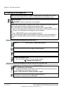
2.6.3 Field weakening control with setting range > 1 : 1.5
CAUTION: Not permitted when Chapter 2.5 was quit with e.m.f. control!
Only when unit is fitted with an SDCS-CON-1 control board!
If the field time constant is known, e.g. from the motor data sheet!
1308 = leave as it is; if appropriate vary between 1...5.
P-gain of the field current controller
1309 =
Enter value of field time constant, if necessary increase by factor 1...2.
I-gain of the field current controller
If possible, check controller behaviour with oscilloscope or CMT tool
11202 = SAVE MOT1 SET
Save the altered values in the non-volatile memory!
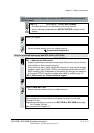
If the field time constant is not known!
1201 = 7 Panel display: FEXC2/3 MAN. TUNIN
Drive Mode: manual balancing of the field current controller
1204 = 4095
1205 = 1000
Ref. value jumps of field current between 25 % and 100 % with POT1 and POT2
11209 = 3
Change between POT1 and POT2 activated
12516 = 0
Switch ON power.
DANGER: System components now energized!
1308 = Match P-gain to field circuit.
1309 = Match I-gain to field circuit.
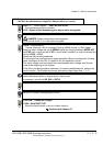
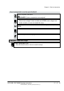
Oscillograph field current feedback via D/A output, or if one is to hand, use CMT
tool to depict it via the TRENDING menu and Parameter
11302.
t
A
B
CD
E
F
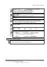
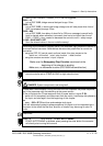
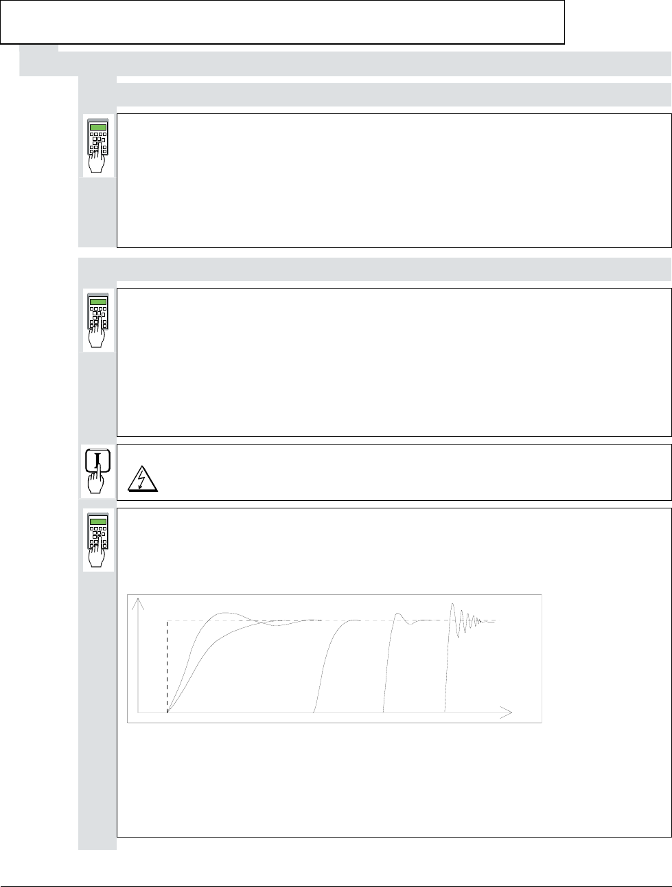
Fig.: Transient response of controller
A: reference value jump
B: undercompensated; reset time and P-gain too small
C: undercompensated; P-gain too small
D: normal
E: slightly overcompensated; when a higher dynamic response is required
F: overcompensated; short reset time and a high P-gain
3ADW000055R0401_DCS500B_Operating Instruction_e_d