


Chapter 4 - Signals and Troubleshooting
IV A 4 - 2 DCS 500B / DCP 500B Operating Instructions
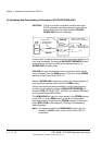
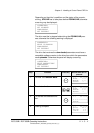
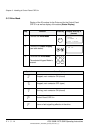
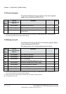
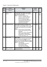
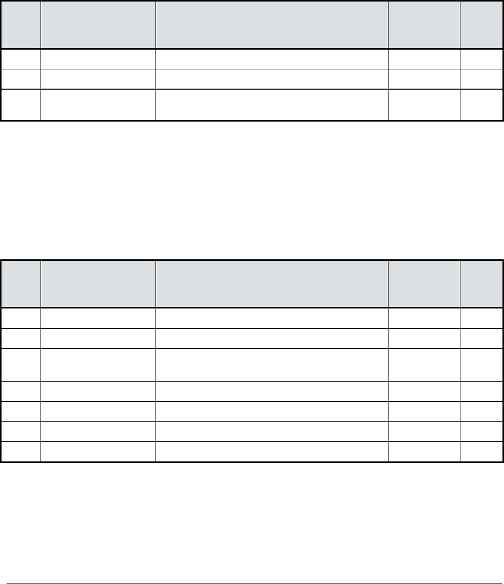
4.2 General messages
The general messages will only be shown on the seven segment
display of the control board SDCS-CON-x.
Code
seven
segm.
display
Text on
LCD of control panel
CDP 31x
Definition
– Remark
8
Not available Program is not running
–
(1)
.
Not available Normal situation, no fault / no alarm signal
–
L
Not available
Indication while loading another firmware
into the drive
–
(1) Units should be switched off and on electrically; if fault occurs again, the PCBs SDCS-POW-1 and SDCS-CON-x
have to be checked and if necessary to be changed.
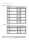
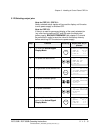
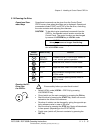
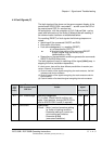
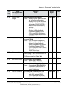
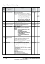
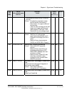
4.3 Starting errors (E)
The starting errors will only be shown on the seven segment display
of the control board SDCS-CON-x.
With starting errors it will not be possible to start the drive.
Code
seven
segm.
display
Text on
LCD of control panel
CDP 31x
Definition
– Remark
E1
Not available ROM memory test error
–
(1)
E2
Not available RAM memory test error
–
(1)
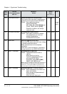
E3
Not available No TC-link board
(not valid for software version S21.1xx)
–
E4
Not available Communic. board SDCS-COM-x faulty
–
(2)
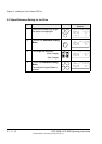
E5
Not available
No control program in memory
–
(3)
E6
Not available
ASIC not O.K.
–
(1)
E7
Not available Parameter FLASH identity test failed
–
(1)
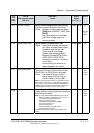
(1) Units should be switched off and on electrically; if fault occurs again, the PCBs SDCS-POW-1 and SDCS-CON-x
have to be checked and if necessary to be changed.
(2) Check communication board, plug in correctly
and if necessary change the board.
(3) Load firmware once more.
3ADW000055R0401_DCS500B_Operating Instruction_e_d