Chapter 2 - Start-Up Instructions
IV A 2 - 14 DCS 500B / DCP 500B Operating Instructions
2.6 Balancing the field supply unit and the e.m.f. controller
When matching the field supply unit to the system conditions, differences in the proce-
dures adopted must be taken into account; these different procedures result from the op-
erating mode used. Only the work of that section has to be performed which deals
with the operating mode actually used in your system!
Constant field current control ⇒ Section 2.6.1
Field weakening control with setting range smaller than 1 : 1.5
⇒ Section 2.6.2
Field weakening control with setting range larger than 1 : 1.5
⇒ Section 2.6.3
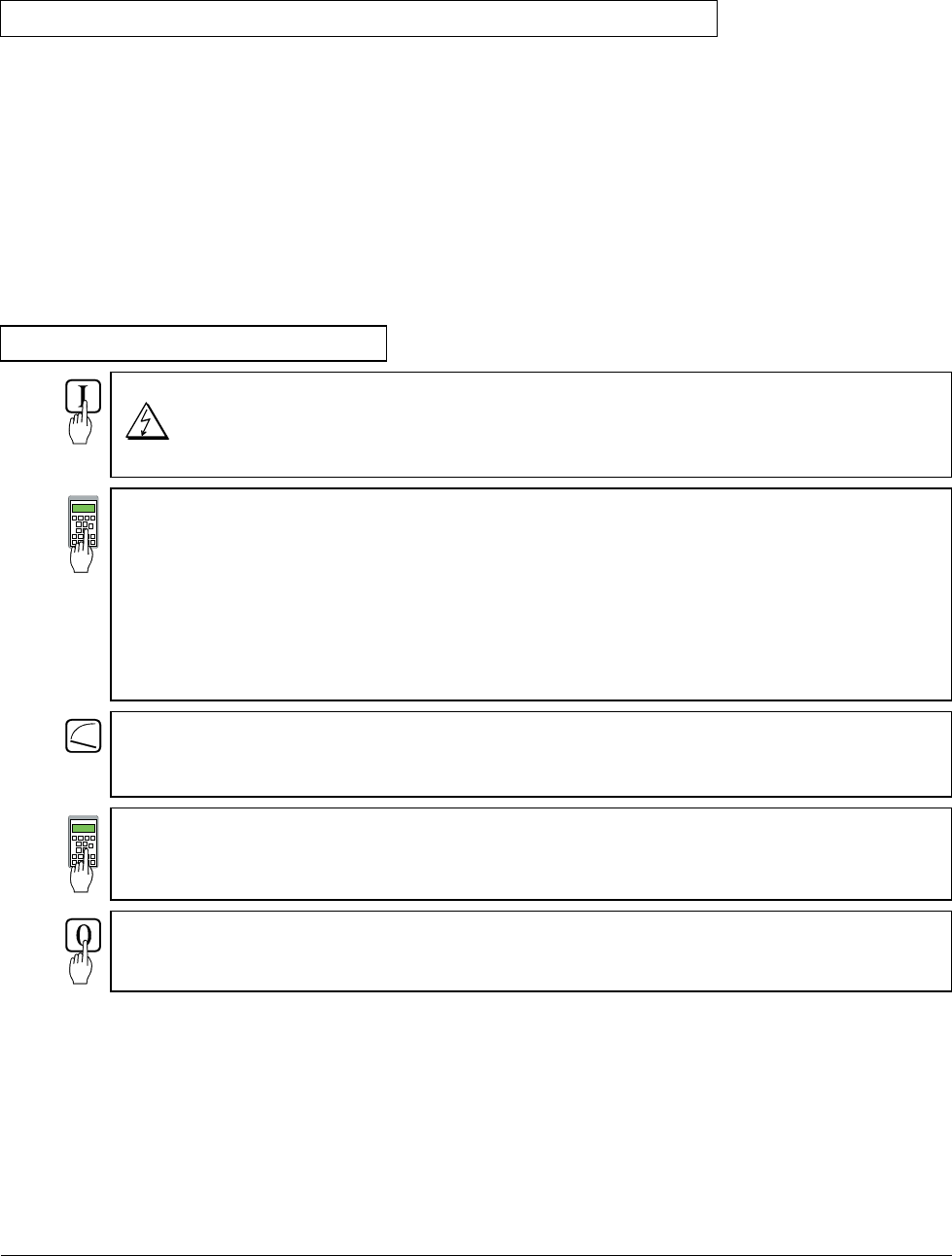
2.6.1 Constant field current control
Switch ON power; start drive.
DANGER: System components now energized!
Drive should run up to 10 % of the speed.
12516 = increase slowly!
Internal reference value is increased; scaling: 20000 corresp. to 100 % speed or
motor voltage, defined with P 501.
Measure motor voltage with the U ARM AC signal by changing between MODE ACT
and PAR; with a value set with P 501, it must remain constant, or must not exceed this
value if 12516 = 20000.
The motor voltage must not exceed the recommended motor voltage; see General
notes at the beginning of this chapter.
Measure speed with manual tacho;
check rated speed when an analog tacho is being used;
if necessary, correct with R9, R48 or R2716.
12516 = 0
Switch OFF power, thus stopping the drive!
Continue with Chapter 2.7
3ADW000055R0401_DCS500B_Operating Instruction_e_d


