


Chapter 3 - Handling of Control Panel CDP 31x
DCS 500B / DCP 500B Operating Instructions IV A 3 - 3
3.3 Panel Functions
The CDP 31x has four different keypad modes:
• Actual Signal Display Mode (ACT)
• Parameter Mode (PAR)
• Function Mode (FUNC)
• Drive Mode (DRIVE) for further extensions
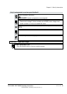
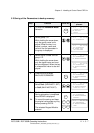
Actual Signal
Display Mode
ACT
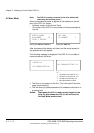
This keypad mode will show, depending on the drive´s history:
• Actual Signals
• Faults
• Fault History Logger
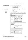
If the ACT-key is pressed immediately after initialization this table is
displayed. If no panel-key is touched for more than one minute the
Actual Signal Display will appear automatically, except when Status
display
or speed reference setting is active. (see chapter 3.13 and
3.15)
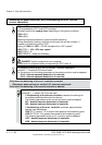
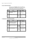
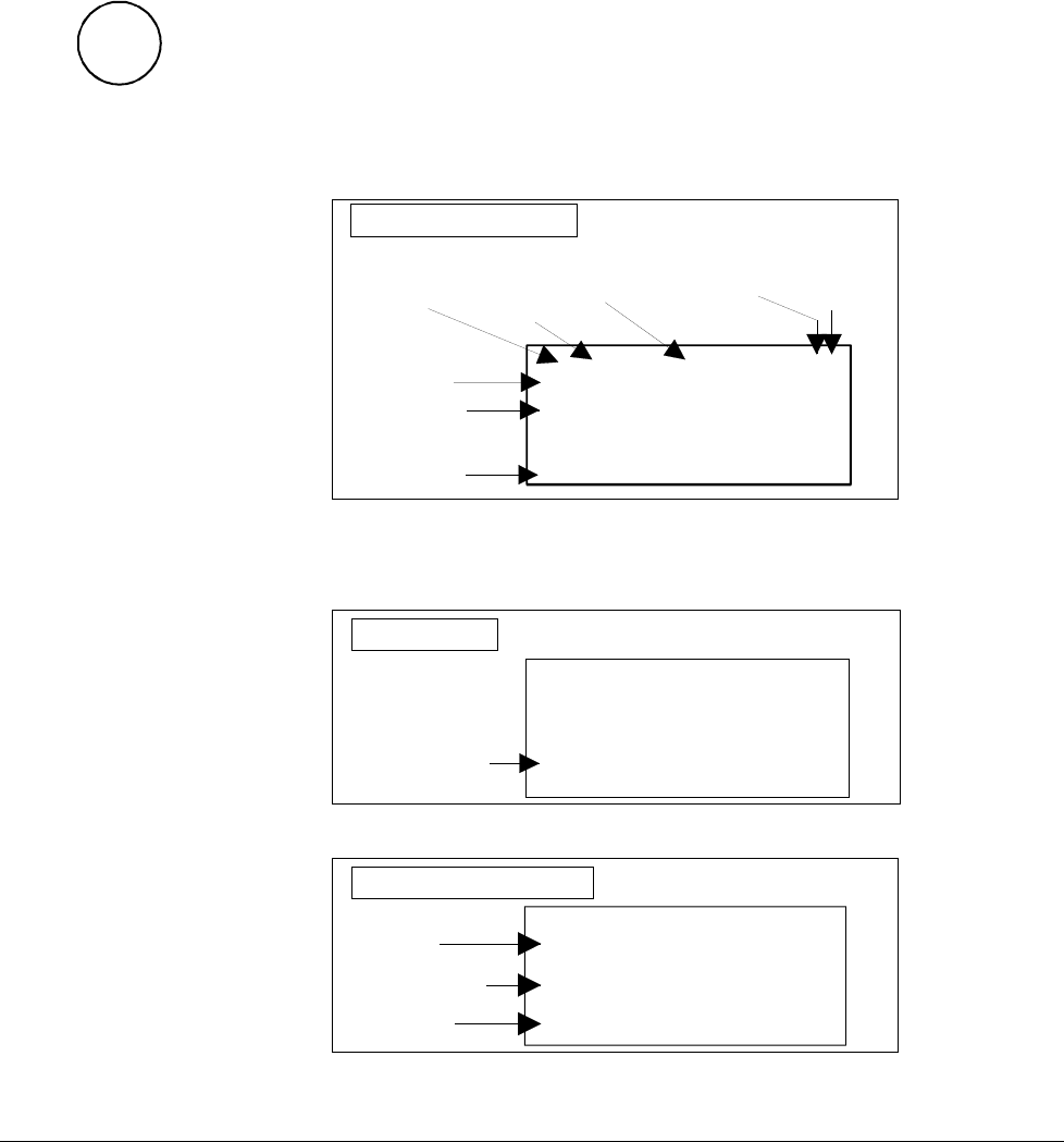
0 L 0.0 rpm 00
SPEED AC 0.0 rpm
CONV CUR 0 A
U ARM AC 0 V
Run Status
I = RUN
0 = STOP
Speed
reference
rpm
Main contactor
status
0 = Open
1 = Closed
Control
Location
L = Local
= Remote
ID-number
of the Drive
Statusrow
Actual Signal
Name, value and unit
_
Cursor shows
the selected row
Actual Signal Display
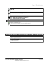
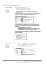
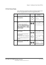
If a fault is effective in the drive, the Fault Display will appear auto-
matically. This will happen with all other modes as well, except the
Drive Mode is active.
Fault Display
0 L 0.0 rpm 00
DCS 500
*** FAULT ***
No ext. FAN ack.
Type of fault or alarm
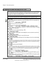
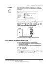
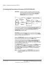
To select Fault History Display see chapter 3.8
1 = last fault
2 = second last fault
...
Total time after
the power up
HHHH:MM:SS.ss
Fault History Display
0 L 0.0 rpm 00
1 LAST FAULT
I/O-Board not found
0000:14:12.64
Fault or alarm name
3ADW000055R0401_DCS500B_Operating Instruction_e_d